Verifying a smart sensor for a crane stability system using formal methods.
Verifying a smart sensor for a crane stability system using formal methods. Troy Huckle SUPERVISOR: AsPr David Kearney ASSOCIATE SUPERVISOR Dr Ivan Lee. Personal Introduction. My Name is Troy Huckle Currently studying LHCP part time. Employed by Robway Crane Safety Systems Pty Ltd. 2.

Verifying a smart sensor for a crane stability system using formal methods.
E N D
Presentation Transcript
Verifying a smart sensor for a crane stability system using formal methods. Troy HuckleSUPERVISOR: AsPr David Kearney ASSOCIATE SUPERVISOR Dr Ivan Lee
Personal Introduction My Name is Troy Huckle Currently studying LHCP part time. Employed by Robway Crane Safety Systems Pty Ltd. 2
Acknowledgment • I like to thank my supervisor AsPr David Kearney for providing direction and support for thesis. I also like to thank my associate supervisor Dr Ivan Lee for helping with guidance to finish of the thesis. Robway Crane Safety Systems Pty Ltd for being flexible so I could work on this thesis.
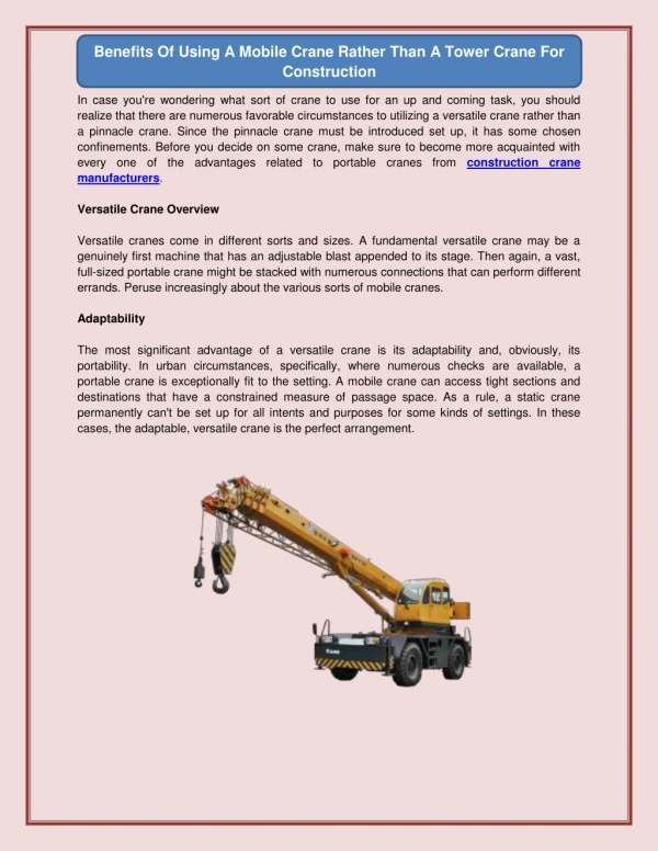
Thesis Introduction What is a crane? Cranes are used for lifting and moving objects in construction and other industries. 4
Crane Safety Safety issues with cranes load drop boom breakage collapse. Tip over. Property damage. People are Injured or killed when things go wrong. 5
Crane Safety Safety measures that can be taken Safety equipment. Operator training. Electronic safety control. Safe Load Indicator (SLI) or Rated Capacity Indicator (RCI) RCI is the crane safety system controller. Micro controller / electronic based system. Analog to digital sensor reading. Displays information to operator like Safe working load (SWL). Drives audio and visual indicators. 6
Crane Safety RCI Software requirements Direct measurement of sensors. Load moment measurement. Allow crane to work in a safe state. Motion cut when in a non safe state. 7
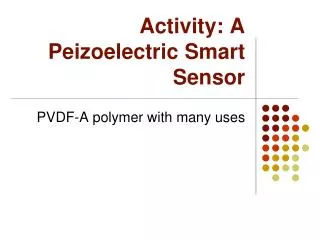
Sensors Sensors What are sensors? A sensor transforms information obtains from an object into an electrical signal. Load pins /cells. Pressure. Angle. Length. Tilt. Data obtain from sensors Voltage. current. Serial data. 8
Smart Sensor Smart Sensors What are smart sensors? Contains intelligence. A smart sensor is an integration of a sensor, interface circuitry, network controller and a microprocessor in a single unit. (Da Silva Sa 2005) Advantages Error detecting. Predictable behaviour. Easy to calibrate and flexible. Less error due cable runs. Easy installation. Can be distributed networked with serial bus. Removes analog measurement from RCI. 9
Sensor Signal Converter Microcontroller Serial Interface Smart sensor block diagram Smart sensor basic block diagram
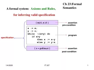
Safety system Eight steps of safety are: (Douglass 1999) 1. Identify the hazards. 2. Determine the risk. 3. Determine safety measures. 4. Create safe design. 5. Create safety requirements. 6. Implement safety. 7. assure the safety process. 8. Test. 11
Safety system Minimise risk in a safety system? Use of safety critical system design methodology, standards, guidelines and qualified software. Examples are: MIRSA C (motor industry guideline for safety critical programs written in C). IEC 61508 Functional Safety of Electrical /electronic safety related systems. Automated Unit Testing (e.g. LDRA Technology, Inc). IAR C compiler MISRA qualified. Integration and system testing. 12
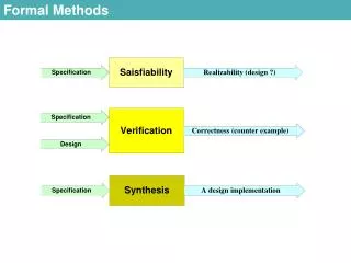
Safety system IEC 61508 standard has some recommendations to avoid the introduction of faults into a system. (Brown 2000) Observations of Guidelines and Standards. Project management. Structured design. Modularisation. Use of well tried components. Semi-formal methods. Checklists. Computer aided design tools. Simulation. Inspection of the hardware or walk through of the hardware. Formal Methods. 13
Modeling Formalmethods Formal methods are mathematically-based techniques for the specification, development and verification of software and hardware systems. Simulation and model checking can be used to check for faults. 14
Model checkers • Model checking software for verification of software. • Holzman (1997) Spin model checker was chosen as the thesis model checker due to the suitability of it to the thesis topic and easy available. • Petri nets used for simulation and verification. • Other model checking solutions investigated: • Goanna a static analysis tool for C/C++ source code based on model checking (Fehnker 2006). • C-BMC a C-bounded model checker for boundary and static code testing (Johnson 2006). • Code wizard a commercial compiler analysis for program rules can check against standards (Johnson 2006).
Petri nets • Petri nets was developed by Carl Adam Petri. • Mathematical defined and graphical step by step process. • Petri nets are made of arcs, places, tokens and transitions. • Transitions consume token and produce tokens.
A D B E C Petri nets • Basic blocks of Petri nets are A)Sequential, B)AND split, C)AND join, D)OR split and EOR join processes.
Petri net model • Fault Status Petri net model
Petri net model • Sensor status & CANBus status
Spin model checker • SPIN model checker is used for verification and simulation. • SPIN is be used to check assertions, unreachable code, deadlocks and safety properties. • SPIN uses PROMELA language and logic properties in linear temporal logic (LTL). • Spin model checker is used to check the model states, which could case a failure (Holzman 1997).
Promela Language Promela is a verification modelling language. Design as a specification language and is targeted for concurrent software systems. Similar to the C language. Allows for dynamic creation of processes. Atomic sequences. 22
Promela petri net model /* Fault Status Petri Net */ byte p1, p2, p3, p4, p5, p6; byte p7, p8, p9, p10, p11; init { p1 = 1; p6 =1; p7 = 1; do ::atomic { (p1 > 0) -> p1--; p2++}; ::atomic { (p2 > 0) -> p2--; p3++ }; ::atomic { ((p2 > 0) && (p6 > 0)) -> p2--; p6--; p4++ }; ::atomic { ((p3 > 0) && (p6 > 0)) -> p3--; p6--; p4++ }; ::atomic { ((p4 > 0) && (p7 > 0)) -> p4--; p7--; p5++ }; ::atomic { (p5 > 0) -> p5--; p1++; p7++; p10++}; ::atomic { (p3 > 0) -> p3--; p9++}; ::atomic { (p8 > 0) -> p8--; p1++; p6++; p7++}; ::atomic { ((p7 > 0) && (p11 > 0)) -> p7--; p11--; p8++ }; ::atomic { (p9 > 0) -> p9--; p11++ }; ::atomic { ((p9 > 0) && (p10 > 0)) -> p9--; p10--; p11++ }; od }
Promela model /* Fault Status */ bool healthFault = false; bool messageFault = false; bool clearFault = true; bool setFault = false; byte semaphore = 1; active proctype faultStatus() { assert( (clearFault == true) && (setFault == false) && (healthFault == false) && (messageFault == false)); assert( semaphore == 1 ); do ::atomic{ ( healthFault && clearFault && (semaphore > 0)) -> semaphore--; clearFault = false; setFault = true; semaphore++; }; ::atomic{ ( messageFault && clearFault && (semaphore > 0)) -> semaphore--; clearFault = false; setFault = true; semaphore++; }; ::atomic{ (( !messageFault && !healthFault ) && setFault && (semaphore > 0)) -> semaphore--; clearFault = true; setFault = false; semaphore++; }; od; }
Validation • Simulation • Asserts • Non progress • Safety properties.
Safety properties • Checking safety properties can highlight problems like unreachable states, deadlocks, and other violations. • The SPIN model checking tool check all states of the model against the safety property claim using a depth first algorithm and identifies where the volitation occurs. • An example is traffic light. A green and right lights should not occur at the same time and a yellow light follows a green light prior to a red light. These can be easily tested for using property checking.
LTL • LTL linear temporal logic. • The LTL symbols used for properties are defined as follows: • - Always, in all cases. • - Logical AND. • - Always implies that it follows on. • <> - Eventually. • - Logical NOT. • - Logical OR. • U - Until.
Properties patterns • Dwyer(1999) has develop a property specification for finite state verification. • This pattern methodology can used be represent LTL claims to reduce complexity. • The pattern mapping and a globally example is given: • (P) - Absence P is False or never occurs. • (P) - Existence P becomes true or eventually. • (P) - Universality P is always true. • <>P U(S P) - Precedence S precedes P or comes before. • (P <>S) - Response S responds to P or comes after.
Transforming LTL in Spin • LTL can be used directly added into Spin. • The LTL symbols used for properties are converted to be used in SPIN are defined as follows: • Always - [] • AND - && • Implies - -> • Eventually - <> • Not - ! • OR || • Equivalent <-> • Until U • Example [] (!(Red && Green))
Never Claims • Spin transforms LTL statement into a never claim. • The never claim file is compiled and then verified against the model.
Never claims • Example: [](!(setFault && clearFault)) produces the below code when transformed by Spin. never { /* !([](!(setFault && clearFault))) */ T0_init: if :: ((clearFault) && (setFault)) -> goto accept_all :: (1) -> goto T0_init fi; accept_all: skip }
RS232 Watch Dog Timer Power Supplies Execition Analog Multiplexer Instrumentation Amplifier Analog Input Microcontroller JTAG CAN Bus Fault Tolerant Health Monitoring SPI Flash Memory Hardware block diagram Hardware block diagram
Sensor description • Connected to the hardware is a dual axis inclinometer. • This sensor provides analogue X and Y direction voltage output signal. • The sensor provides a measuring range +- 10 degrees of tilt. This voltage is required to be transformed into digital value and transmitted on a CAN bus in a message packet.
Hardware Schematic • Analog input, multiplexer and Amplification
Hardware Schematic • Microcontroller and SPI flash memory
Hardware Schematic • RS232 and Fault tolerant CANBUS
Hardware Schematic • Power supplies and health check
Hardware PCB • 4 Layer PCB
Outcomes • Model of smart sensor • Petri net model developed. • Promela model developed. • Simulation of the model. • LTL safety properties developed. • A verified Promela model using the Spin model checker. • Hardware smart sensor • A hardware schematic and parts list. • A electronic printed circuit board layout.
Conclusion • Design methodology, standards, guidelines and qualified software can be used to minimise risk in a safety critical system. • Formal methods like model checking can be used to check for software faults and to verify a safety system. • Introduction of faults can be reduced by using Spin model checker. • Modelling of a system can provide useful information on a system prior to development of the system.
Future Work • Graphical tool suited to safety critical applications. • Auto translate graphical model into Promela language and Translation of Promela language into C language.
Questions? Questions? 44
References • Brown, S 2000, 'Overview of IEC 61508. Design of electrical/ electronic/ programmable electronic safety-related systems', Computing & Control Engineering Journal, vol. 11, no. 1, pp. 6-12. • Da Silva Sa, J, da Silva, JJ, Wanzeller, MG & da Rocha Neto, JSAdRNJS 2005, 'Monitoring of Temperature Using Smart Sensors Based on CAN Architecture', paper presented at the Electronics, Communications and Computers, 2005. CONIELECOMP 2005. Proceedings. 15th International Conference on. • Douglass, BP 1999, Doing Hard Time: Developing Real-Time Systems With Uml, Objects, Frameworks, and Patterns, Addison-Wesley Professional. • Dwyer, MB, Avrunin, GS & Corbett, JC 1999, 'Patterns in property specifications for finite-state verification', Software Engineering, 1999. Proceedings of the 1999 International Conference on, pp. 411-420. • Holzmann, GJ 1997, 'The model checker SPIN', Software Engineering, IEEE Transactions on, vol. 23, no. 5, pp. 279-295. • Johansson, KH, Torngren, M & Nielsen, L 2005, 'Vehicle Applications of Controller Area Network', New York, NY: Birkhauser Boston, Inc, 2005., pp. 741-765.
References • Saha, I & Roy, S 2007, 'A Finite State Analysis of Time-Triggered CAN (TTCAN) Protocol Using Spin', Proceedings of the International Conference on Computing: Theory and Applications, pp. 77-81.