Download

1 / 14
170 likes | 679 Vues
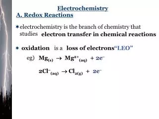
Analytical Electrochemistry : Potentiometry. Introduction Goals and Objectives Potentiometry Timeline Potentiometric Theory Instrumentation pH Electrodes Experiments Common Troubleshooting Tips References. Introduction

E N D
Analytical Electrochemistry : Potentiometry • Introduction • Goals and Objectives • Potentiometry Timeline • Potentiometric Theory • Instrumentation • pH Electrodes • Experiments • Common Troubleshooting Tips • References Introduction This module provides an introduction to the measurement technique of potentiometry. It is intended to be a primary learning tool for a student in a Quantitative Analysis or Analytical Chemistry course and as a review resource for a student in Instrumental Analysis. It could also serve as a beginning resource for new practitioners. If you have ever used a pH meter, then you have already performed potentiometry, an electrochemical method in which the potential of an electrochemical cell is measured while little to no current is passed through the sample. In a potentiometric measurement, an indicator electrode responds to changes in the activity, or “effective concentration” of the analyte. A potential, or voltage, that develops at the interface between the electrode and the analyte solution is measured relative to a reference electrode. This potential will be proportional to the amount of analyte in the sample. An illustration of one type of indicator electrode, the hydrogen ion or pH electrode, is shown in the upper right-hand corner of this page. Click hereto continue reading the introduction. Erin M. Gross1, Richard S. Kelly2, and Donald M. Cannon, Jr.3 1Department of Chemistry, Creighton University, Omaha, NE 2Department of Chemistry, East Stroudsburg University, East Stroudsburg, PA 3Department of Chemistry, University of Iowa, Iowa City, IA This work is licensed under a Creative Commons Attribution-Noncommercial-Share Alike 2.5 License
Analytical Electrochemistry : Potentiometry • Introduction • Goals and Objectives • Potentiometry Timeline • PotentiometricTheory • Instrumentation • pH Electrodes • Experiments • Common Troubleshooting Tips • References • Goals and Objectives • After completion of this e-Module, you should be able to: • Describe the basic concepts of making a potentiometric measurement. • Name some applications of potentiometry. • Know the difference between a reference electrode and an indicator electrode. • Describe the reactions of the typical reference electrodes. • Define liquid junction potential and boundary potential. • Describe how ion-selective electrodes (ISEs) function. • Describe how both a pH electrode and a pH meter work. • Describe the errors involved in pH measurements. • Perform basic troubleshooting while making a pH measurement. • Use the Nernst equation to perform calculations for potentiometric measurements. • Click hereto get started!
Analytical Electrochemistry : Potentiometry • Introduction • Goals and Objectives • Potentiometry Timeline • PotentiometricTheory • Instrumentation • pH Electrodes • Experiments • Common Troubleshooting Tips • References Potentiometry Timeline Shown below are major milestones in the development of potentiometry. Additional information is available in the references cited. Adapted from references 1- 7. Click herefor Potentiometric Theory.
Analytical Electrochemistry : Potentiometry Introduction Goals and Objectives Potentiometry Timeline Potentiometric Theory Junction Potentials Direct Indicator Electrodes Ion-Selective Electrodes Reference Electrodes Nernst Equation Instrumentation pH Electrodes Experiments Common Troubleshooting Tips References • Potentiometric Theory • The origin of the measured potential at an indicator electrode is • most generally the separation of charge across an interface • between solutions of differing ionic strengths (an inner solution • at fixed analyte activity and an outer solution with variable • analyte activity). • The mechanism leading to this charge separation varies with • electrode type. After defining what is meant by a junction • potential, we will consider two types of indicator electrodes: • the metallic direct indicator electrode, whose response involves a surface or solution redox reaction, and • the membrane electrode, or ion-selective electrode (ISE). • Click hereto learn about junction potentials.
Analytical Electrochemistry : Potentiometry Introduction Goals and Objectives Potentiometry Timeline Potentiometric Theory Junction Potentials Direct Indicator Electrodes Ion-Selective Electrodes Reference Electrodes Nernst Equation Instrumentation pH Electrodes Experiments Common Troubleshooting Tips References Junction Potentials A potential develops at any interface, or junction, where there is a separation of charge. For example, a potential can develop when a metal electrode comes in contact with a solution containing its cation. A potential of this type can be described using the Nernst Equation. A potential can also develop when electrolyte solutions of differing composition are separated by a boundary, such as a membrane or a salt bridge (a gel-filled tube containing an inert electrolyte that connects half-cells to allow charge neutrality to be maintained). The two solutions may contain the same ions, just at different concentrations or may contain different ions altogether. These ions have different mobilities, which means that they move at different rates. Click herefor more about junction potentials.
Analytical Electrochemistry : Potentiometry Introduction Goals and Objectives Potentiometry Timeline Potentiometric Theory Junction Potentials Direct Indicator Electrodes Ion-Selective Electrodes Reference Electrodes Nernst Equation Instrumentation pH Electrodes Experiments Common Troubleshooting Tips References Direct Indicator Electrodes The simplest type of direct indicator electrode is a metal, M, in contact with a solution containing its own cation, M+. At the metal-solution interface, a potential develops that is proportional to the activity of the metal ion in solution. The potential can be measured directly with respect to a reference electrode using the simple arrangement shown at right. Inert metal electrodes like Pt or Au can be used as indicator electrodes for ions involved in redox reactions that occur in solution but do not include the metallic form of the analyte. Click herefor more on direct indicator electrodes.
Analytical Electrochemistry : Potentiometry Introduction Goals and Objectives Potentiometry Timeline Potentiometric Theory Junction Potentials Direct Indicator Electrodes Ion-Selective Electrodes Reference Electrodes Nernst Equation Instrumentation pH Electrodes Experiments Common Troubleshooting Tips References Ion-Selective Electrodes Click here to learn more about ion-selective electrodes. So far you have learned that in the technique of potentiometry, the potential, or voltage, of an electrochemical cell is measured. The cell consists of both an indicator and reference electrode. Since the potential of the reference electrode is constant, it is the potential developed at the indicator electrode that contains information about the amount of analyte in a sample. During the measurement, there is little to no current flow. An electrochemical cell for making a potentiometric measurement with a membrane electrode (also known as an ion-selective electrode, ISE) is shown in the figure to the right. As you can see the main difference between an ISE and the direct indicator electrode is in the ISE’s composition.
Analytical Electrochemistry : Potentiometry Introduction Goals and Objectives Potentiometry Timeline Potentiometric Theory Junction Potentials Direct Indicator Electrodes Ion-Selective Electrodes Reference Electrodes Nernst Equation Instrumentation pH Electrodes Experiments Common Troubleshooting Tips References Reference Electrodes It should be clear by now that at least two electrodes are necessary to make a potential measurement. As Kissinger and Bott have so perfectly expressed, “electrochemistry with a single electrode is like the sound of one hand clapping” (http://currentseparations.com/issues/20-2/20-2d.pdf). In potentiometry, those two electrodes are generally called the indicator electrode and the reference electrode. The indicator electrode possesses some characteristic that allows it to selectively respond to changes in the activity of the analyte being measured. For the measured potential to have meaning in this context, the reference electrode must be constructed so that its composition is fixed and its response is stable over time, with observed changes in measured potential due solely to changes in analyte concentration. Click hereto learn more about reference electrodes.
Analytical Electrochemistry : Potentiometry Introduction Goals and Objectives Potentiometry Timeline Potentiometric Theory Junction Potentials Direct Indicator Electrodes Ion-Selective Electrodes Reference Electrodes Nernst Equation Instrumentation pH Electrodes Experiments Common Troubleshooting Tips References Nernst Equation The technique of potentiometry involves the measurement of cell potentials under conditions of no current flow. In the electrochemical cell, if a high impedance device like a voltmeter, is placed between the two half cells, no current will flow between the two compartments. As we have seen, it is possible under these conditions to measure the potential difference that exists between the two electrodes. For cells with all reactants present at unit activity, the measured cell potential will be the standard cell potential, E0cell. In real applications of potentiometry, reactant activities are seldom (read never) equal to unity, and measured cell potentials move away from those that result from the tabulated values of E0. A fundamental expression for characterizing redox systems under equilibrium conditions is the Nernst equation. One usually has encountered this expression early in their study of electrochemistry, perhaps in a general chemistry course long ago. Click hereto learn more about the Nernst equation.
Analytical Electrochemistry : Potentiometry • Introduction • Goals and Objectives • Potentiometry Timeline • Potentiometric Theory • Instrumentation • pH Electrodes • Experiments • Common Troubleshooting Tips • References Instrumentation You have realized by now that potentiometric measurements are fairly easy to make from the standpoint of instrumentation. In addition to the indicator electrode and the reference electrode, the only remaining component is a device used to measure the potential difference that exists between the two electrodes. If you have been with us to this point, you should remember that potentiometric measurements are ideally made under conditions of very little current flow. This means that the resistance (impedance to current flow) in the electrochemical cell must be very high (up to 100 MW). This is usually not a problem due to the nature of the indicator electrode, but the measurement of potential under these conditions requires the use of a device whose input resistance is even larger than the cell resistance. Click hereto learn more about instrumentation.
Analytical Electrochemistry : Potentiometry • Introduction • Goals and Objectives • Potentiometry Timeline • Potentiometric Theory • Instrumentation • pH Electrodes • Experiments • Common Troubleshooting Tips • References pH Electrodes The most widely used ion-selective electrode is the glass pH electrode, which utilizes a thin glass membrane that is responsive to changes in H+ activity. F. Haber, in 1901, was the first person to observe that the voltage of a glass membrane changed with the acidity of a solution. In 1906, M. Cremer observed the pH dependence of measured potential across a thin glass membrane. Today, pH sensitive glasses are manufactured primarily from SiO2 which are connected via a tetrahedral network with oxygen atoms bridging two silicon atoms (see an interactive 3d structure at (http://www.geo.ucalgary.ca/~tmenard/crystal/quartz.html). In addition, the glasses are made to contain varying amounts of other metal oxides, like Na2O and CaO. Oxygen atoms within the lattice that are not bound to two silicon atoms possess a negative charge, to which cations can ion pair. In this way, ions (primarily Na+) are able to diffuse slowly in the lattice, moving from one charge pair site to another. While the membrane resistance is very high (~100 MW), this movement of cations within the glass allows a potential to be measured across it. Click hereto learn more about pH electrodes.
Analytical Electrochemistry : Potentiometry • Introduction • Goals and Objectives • Potentiometry Timeline • Potentiometric Theory • Instrumentation • pH Electrodes • Experiments • Common Troubleshooting Tips • References • Experiments • Potentiometric Titration of an Unknown Monoprotic Weak Acid • Determination of Chloride Using Potentiometry • Fluoride Ion by Direct Potentiometry/Standard Addition
Analytical Electrochemistry : Potentiometry • Introduction • Goals and Objectives • Potentiometry Timeline • Potentiometric Theory • Instrumentation • pH Electrodes • Experiments • Common Troubleshooting Tips • References Common Troubleshooting Tips While understanding the underlying general concepts of potentiometry is a useful first step at becoming a regular "potentiometric practitioner", experience is also a great resource for effectively conducting these types of measurements. Through experience comes familiarity with common "problem areas" of this field. This page is intended to present some troubleshooting tips. It is not our intention to replace recommendations outlined in manufacturer literature. Before specific discussion on common problem areas, the subtle nuance differences between efforts in calibration methods and quality control (QC) must be highlighted. Calibration and QC methods are complementary to one another and are often integrated into a method validation program that defines the overall reliability. Calibrations give analytical methods an initial quantitative starting point, whereas QC validates the developed calibration model. Click hereto learn more about troubleshooting.
Analytical Electrochemistry : Potentiometry • Introduction • Goals and Objectives • Potentiometry Timeline • Potentiometric Theory • Instrumentation • pH Electrodes • Experiments • Common Troubleshooting Tips • References • References • Cremer, M,. Z. Biol.1906, 47, 562. • Buck, R.P. and Lindner, E. Anal. Chem. 2001, 73, 88A. • Frant, M.S., Analyst, 1994, 119, 2293. • Frant, M.S. and Ross, J.W., Science, 1966, 154, 1553. • Ross, J.W., Science, 1967, 156, 1378. • Simon, W., Swiss Pat., 479870, 1969. • Frant, M.S. and Ross, J.W., Science, 1970, 167, 987. • Bakker, E. and Pretsch, E., Anal. Chem., 2002, 74, 420A. • Meyerhoff, M.E. and Opdycke, W.N. In Advances in Clinical Chemistry, vol. 25; Spiegel, H.E., Ed.; Academic Press, Inc., Orlando, 1986, pp. 1-47. • Bakker, E.; Buhlmann, P.; Pretsch, E. Talanta, 2004, 63, 3. • Wang, J. Analytical Electrochemistry, 3rd ed.; Wiley: Hoboken, NJ 2006, pp. 165-200. • Skoog, D.A., Holler, F.J., Crouch, S.R., Principles of Instrumental Analysis, 6th ed.; Thomson Brooks/Cole: Belmont, CA, 2007. • Buhlmann, P.; Pretsch, E.; Bakker, E. Chem Rev. 1998, 98, 1593.