Download

1 / 107
1.07k likes | 1.46k Vues
Application of Infrared Spectroscopy Chapter 17. Dr. Nizam M. El-Ashgar Chemistry Department Islamic University of Gaza. Infrared spectrometry is applied to the qualitative and quantitative determination of molecular species of all types.

E N D
Application of Infrared Spectroscopy Chapter 17 Dr. Nizam M. El-Ashgar Chemistry Department Islamic University of Gaza
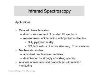
Infrared spectrometry is applied to the qualitative and quantitative determination of molecular species of all types. • The most widely used region is the mid-infrared that extends from about 400 to 4000 cm-1 (2.5 to 25 m). (Absorption, reflection and emission spectra are employed) • The near-infrared region from 4000 to 14,000 cm-1 (0.75 to 2.5 m) also finds considerable use for the routine quantitative determination. (water, CO2, low conc. Hydrocarbons, amine nitrogen, many other compounds) • The far-infrared region has been for the determination of the structures of inorganic and metal-organic species.
MID-INFRARED ABSORPTION SPECTROMETRY Sample Handling • No good solvents exist that are transparent throughout the region of interest. • As a consequence, sample handling is frequently the most difficult and time-consuming part of an infrared spectrometric analysis. • Gases:The spectrum of a low-boiling liquid or gas can be obtained by permitting the sample to expand into an evacuated cylindrical cell equipped with suitable windows.
Gas samples • A gas sample cell consists of a cylinder of glass or sometimes a metal. The cell is closed at both ends with an appropriate window materials (NaCl/KBr) and equipped with valves or stopcocks for introduction of the sample. • Long path length (10 cm) cells – used to study dilute (few molecules) or weakly absorbing samples. • Multipass cells – more compact and efficient instead of long-pathlength cells. Mirrors are used so that the beam makes several passes through the sample before exiting the cell. (Effective pathlength 10 m). • To resolve the rotational structure of the sample, the cells must be capable of being evacuated to measure the spectrum at reduced pressure. • For quantitative determinations with light molecules, the cell is sometimes pressurized in order to broaden the rotational structure and all simpler measurement.
Solutions: • A convenient way of obtaining infrared spectra is on solutions prepared to contain a known concentration of sample. • This technique is somewhat limited in its applications, however, by the availability of solvents that are transparent over significant regions in the infrared. Solvents: • No single solvents is transparent throughout the entire mid-infrared region. • Water and alcohols are seldom employed, not only because they absorb strongly, but also because they attack alkali-metal halides, the most common materials used for cell windows.
Cells: • Sodium chloride windows are most commonly employed; even with care, however, their surfaces eventually become fogged due to absorption of moisture. • Polishing with a buffing powder returns them to their original condition. Liquids: • When the amount of liquid sample is small or when a suitable solvent is unavailable, it is common practice to obtain spectra on the pure (neat) liquid. • A drop of the neat liquid is squeezed between two rock-salt plated to give a layer that has a thickness of 0.01 mm or less. • The two plates, held together are then mounted in the beam path. Such a technique does not give reproducible transmittance data, but the resulting spectra are usually satisfactory for qualitative investigations.
Carbon Tetrachloride no C-H! C-Cl stretch
Solids: • Most organic compounds exhibit numerous absorption peaks throughout the mid-infrared region, and finding a solvent that does not have overlapping peaks is often impossible. • As a consequence, spectra are often obtained on dispersions of the solid in a liquid or solid matrix. Pelleting: • One of the most popular techniques for handling solid samples has been KBr pelleting. • A milligram or less of the finely ground sample is mixed with about 100 mg of dried potassium bromide powder. • The mixture is then pressed in a die at 10,000 to 15,000 pounds per square inch to yield a transparent disk. • The disk is then held in the instrument beam for spectroscopic examination.
Mulls (suspension): • Infrared spectra of solids that are not soluble in an infrared-transparent solvent or are not conveniently pelleted in KBr are often obtained by dispersing the analyte in a mineral oil or fluorinated hydrocarbon mull. • Mulls are formed by grinding 2 to 5 mg of the finely powdered sample in the presence of one or two drops of a heavy hydrocarbon oil (Nujol). • If hydrocarbon bands interfere, Fluorolube, a halogenated polymer, can be used. • The resulting mull is then examined as a film between flat salt plates.
Determination of cell thickness • Determination of thickness (b) : Pathlength of thin IR sample holder can be determined by observation of the interference patterns associated with constructive interference from reflection of light from the two internal surfaces of cell: • Insertion of empty cell in the light path (reference beam passed unobstructed to monochromator). • Interference fringe (maxima and minima) occurs. • Maxima: internal reflection of radiation by cell surfaces at distance of multiple N of wavelength of radiation. • 2b = N 2b/N = N = 2b/ • Number if interference fringes N between two known wavelengths • N = 2b/ 1 – 2b/ 2
Qualitative Analysis • Used for identifying organic, inorganic, and biological species. • The time required to perform a structural determination was reduced by a factor of ten, one hundred, or even one thousand. Identification of an organic compound is a two-step process. • The first step involves determining what functional groups are most likely present by examining the group frequency region. • The second step then involves a detailed comparison of the spectrum of the unknown with the spectra of pure compounds that contain all of the functional groups found in the first step. The fingerprint region, from 1200 to 600 cm -1 is particularly useful because small differences in the structure and constitution of a molecule result in significant changes in the appearance and distribution of absorption peaks in this region.
IR Spectrum Baseline Absorbance/Peak • No two molecules will give exactly the same IR spectrum (except enantiomers) • Group frequency region (Simple stretching): 1200-3500 cm-1 • Fingerprint region (Complex vibrations): 400-1200 cm-1,
Group Frequencies: • The approximate frequency (or wavenumber) at which an organic functional group, such as C=O, C=C, C—H, CC, or O—H absorbs infrared radiation can be calculated from the masses of the atoms and the force constant of the bond between them. • These frequencies, called group frequencies, are seldom totally invariantغير ثابتة القيمة because of interactions with other vibrations associated with one or both of the atoms composing the group. • A range of frequencies can be assigned within which it is highly probable that the absorption peak for a given functional group will be found. • Are usually due to stretching vibrations of diatomic units
The “Fingerprint” Region: • Small differences in the structure and constitution of a molecule result in significant changes in the distribution of absorption peaks in this region of the spectrum that extends from about 1200 to 700 cm-1. • As a consequence, a close match between two spectra in this fingerprint region constitutes strong evidence for the identity of compounds yielding the spectra. • Exact interpretation of spectra in this region is seldom possible because of the complexity of the spectra.
Correlation chart: General regions of an infrared spectrum • Note that the blue coloured sections above the dashed line refer to stretching vibrations, and the green coloured band below the line encompasses bending vibrations.
Computer Search Systems: • Virtually all infrared instrument manufactures now offer computer search systems to assist chemist in identifying compounds from stored infrared spectral data. • The position and relative magnitudes of peaks in the spectrum of the analyte are determined and stored in memory to give a peak profile, which can then be compared with profiles of pure compounds stored. • The computer then matches profiles and prints a list of compounds having spectra similar to that of the analyte. • Usually the spectrum of the analyte and that of each potential match can then be shown simultaneously on the computer display for comparison.
Infrared interpretation • Step 1 • Look first for the carbonyl C=O band. • Look for a strong band at 1820-1660 cm-1. This band is usually the most intense absorption band in a spectrum. It will have a medium width. If you see the carbonyl band, look for other bands associated with functional groups that contain the carbonyl by going to step 2. • If no C=O band is present, check for alcohols and go to step 3. • Step 2 • If a C=O is present you want to determine if it is part of an acid, an ester, or an aldehyde or ketone. At this time you may not be able to distinguish aldehyde from ketone.
ACID • Look for indications that an O-H is also present. • It has a broad absorption near 3300-2500 cm-1. • This actually will overlap the C-H stretch. There will also be a C-O single bond band near 1100-1300 cm-1. • Look for the carbonyl band near 1725-1700 cm-1. • ESTER • Look for C-O absorption of medium intensity near 1300-1000 cm-1. • There will be no O-H band.
ALDEHYDE • Look for aldehyde type C-H absorption bands. These are two weak absorptions to the right of the C-H stretch near 2850 cm-1 and 2750 cm-1 and are caused by the C-H bond that is part of the CHO aldehyde functional group. • Look for the carbonyl band around 1740-1720 cm-1. • KETONE • The weak aldehyde CH absorption bands will be absent. Look for the carbonyl CO band around 1725-1705 cm-1. • Step 3 • If no carbonyl band appears in the spectrum, look for an alcohol O-H band. • ALCOHOL • Look for the broad OH band near 3600-3300 cm-1 and a C-O absorption band near 1300-1000 cm-1.
Step 4 • If no carbonyl bands and no O-H bands are in the spectrum, check for double bonds, C=C, from an aromatic or an alkene. • ALKENE • Look for weak absorption near 1650 cm-1 for a double bond. There will be a CH stretch band near 3000 cm-1. • AROMATIC • Look for the benzene, C=C, double bonds which appear as medium to strong absorptions in the region 1650-1450 cm-1. The CH stretch band is much weaker than in alkenes.
C-H stretching region • Alkanes C-H sp3 stretch < 3000 cm-1 • Alkenes C-H sp2 stretch > 3000 cm-1 • Alkynes C-H sp stretch ~ 3300 cm-1 • C-H Bending region • CH2 bending ~ 1460 cm-1 • CH3 bending (asym) appears near the same value • CH3 bending (sym) ~ 1380 cm-1
Step 5 • If none of the previous groups can be identified, you may have an alkane. • ALKANE • The main absorption will be the C-H stretch near 3000 cm-1. The spectrum will be simple with another band near 1450 cm-1. • Step 6 • If the spectrum still cannot be assigned you may have an alkyl halide. • ALKYL BROMIDE • Look for the C-H stretch and a relatively simple spectrum with an absorption to the right of 667 cm-1.
1-Hexene sp2 C-H C=C stretch out of plane bendings (oops) sp3 C-H stretch
Toluene sp2 C-H sp3 C-H aromatic C=C aromatic oops
Cyclohexanol bending O-H stretch C-O stretch sp3 C-H stretch
1-Butanamine N-H bend CH2 CH3 bend N-H stretch doublet sp3 C-H stretch
4-Methyl-2-pentanoneC-H < 3000, C=O @ 1715 cm-1 C-H stretch C=O stretch
Acetophenone C-H stretch aromatic C=C conj C=O
Strengths and Limitations • IR alone cannot determine a structure • Some signals may be ambiguous • The functional group is usually indicated • The absence of a signal is definite proof that the functional group is absent • Correspondence with a known sample’s IR spectrum confirms the identity of the compound
Quantitative Applications • Quantitative infrared absorption methods differ somewhat from ultraviolet/visible molecular spectroscopic methods because of the greater complexity of the spectra, the narrowness of the absorption bands, and the instrumental limitations of infrared instruments. • Quantitative data obtained with infrared instruments are generally significantly inferior in quality to data obtained with ultraviolet/visible spectrophotometers.
Quantitative Analysis • IR more difficult than UV-Vis because • narrow bands (variation in e) • complex spectra • weak incident beam • low transducer sensitivity • solvent absorption • IR mostly used for rapid qualitative but notquantitative analysis • Beer’s law failure • Long optical path-length required • Regular FT-IR is worse than UV-VIS • Exception - Tunable IR laser, quantum cascade laser, OPO
Absorbance measurements: • In UV/Vis: matched absorption cells for solvent and solution are employed and so A = log (I solvent /I solution) • Blank cancel out the effects of: • Radiation losses due to reflection • Scattering and absorption by solvent • Absorption by container windows • In IR: Reference cell (blank) seldom employed because: • Difficulty in obtaining identical cells. • IR cells have short bathlengths (difficult to duplicate) • Cell windows rapidly attacked (atmosphere & solvent)
Deviations from Beer’s law • More common than in UV/Vis • IR absorption bands are relatively narrow • Dispersive instruments: low intensity sources and low sensitivity detectors require the use of relatively wide monochromator slit widths. • Non linear relationship between absorbance and concentration. • Quantitative data from dispersive IR Instruments are less precise and accurate than those from UV/Vis instruments. • FT instruments are better than dispersive ones Empirical calibration curves are often required for IR quantitative work