Micromouse
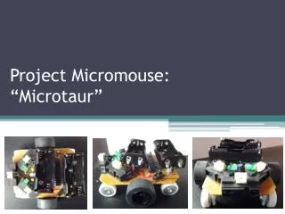
Micromouse. Ryan Bidlack Jason Wells. Problem Statement. Design and Build an autonomous ‘mouse’ that will navigate its own way through a maze. Background.


Micromouse
E N D
Presentation Transcript
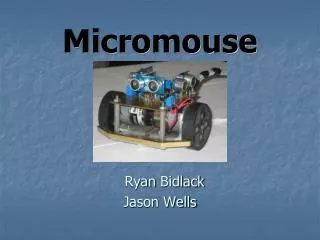
Micromouse Ryan Bidlack Jason Wells
Problem Statement • Design and Build an autonomous ‘mouse’ that will navigate its own way through a maze
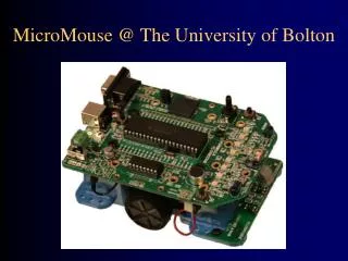
Background • Micromouse is an autonomous self contained machine designed to get to the center of a maze in the shortest possible time. A Micromouse essentially comprises of a drive motor or motors to move it; a steering and turning method; sensors to detect the presence or absence of maze walls; sensors or control logic to oversee the action of the rest and keep the vehicle 'on track' or to solve the maze; batteries to provide power. (techfest.org)
Event • Techfest 2009 • Student and Professional categories • This event is held every year in different locations around the world • Held in Bombay, India this year • INR 45,000 in prizes (approx $1000 USD)
Mouse Requirements • A Micromouse shall be self contained. • Micromouse must follow size constraints of 250 mm wide by 250 mm long. No height limit. • Micromouse must not be powered by a combustion or nuclear process • A Micromouse shall not leave anything behind while negotiating the maze. • A Micromouse shall not jump over, climb, scratch, damage, or destroy the walls of the maze.
Workload Breakup • Ryan Bidlack • Mechanical Design, Sensor control software, sensor interfacing. • Jason Wells • Mechanical Design, Motor control software, Circuit board design.
Maze characteristics • Black Painted Plywood floor • White painted plywood walls • 7 inches between walls
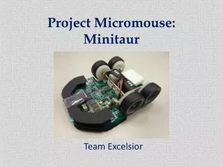
Drive train Wheels in center DC motors 2.375” rubber wheels Sensors and Control HC08 Ping sensors LM298 motor driver Navigation Look for First opening Left side has priority Final Design
System Diagram Wall Wall Ping Ping Motor Control HCS 08 Ping Wall
Custom Board • Piece of the mouse frame • Same size as motor plate • Holds three ping sensors
Electrical Concepts Left Motor 9V Battery 9V Motor Control 5V reg. 9V 9V Right Motor 9V 5V Ping Ping Mouse Main Board 9V HCS 08 Ping
Motor Drivers • L298 Motor Driver Board • 6-24Vin • 5V at 4amps output
Motor Control Software Sample Code PTBDD= 0x1f; Sets PTBD 0-3 to outputs both_motors_forward lda #%00010101 ;sets enable pin, and sets L2 and L4 high sta PTBD rts
90 deg. left calculation • 7.46” circumference wheel = C • 130 rpm motor = rpm • Robot speed (in/min) = C * rpm = 969 • Robot speed (in/s) = 16.16
90 deg. left calculation • Robot turns 17.27” circumference • 90 deg. = ¼ arc = 4.3” circumference • 90 deg. time = 4.3” / robot speed (in/s) • 90 deg. Time = 266 mS
90 deg. left software ninety_degree_left lda #%00001101 ; motors turning opposite ways sta PTBD ldhx #266 ; this is where the 90 deg. time gets put in jsrdelay_xhms lda #%000000001 ;motors stop sta PTBD rts
Sensors • Parallax Ping Sensor • Published working range of 2cm-3m • Tested Working range of 1cm-3m • When distance is under 1cm a longer pulse is returned • Pings are set back on mouse to prevent false readings • Sensor returns a value into a variable
Sensor Programming read_front_sensor: bclr 0,PTAD ;making port an output bset 0,PTADD nop ;wastes time bset 0,PTAD jsr delay_10us ;min 2us, max 750us, output pulse bclr 0,PTAD bclr 0,PTADD ;making port an input echo_start: lda PTAD bit #1 ;looks for the start of the return pulse beq echo_start clrx echo_time: incx jsr delay_10us ; changing this time delay changes the resolution jsr delay_1ms ;looks for the end of the pulse lda PTAD bit #1 bne echo_time pshx pula rts
Sensor Calibration • Sensor resolution is adjusted by changing a time delay • With a 10us delay there is no chance of overflowing the counter
Budget Total Allocated funds $400 Maze materials -$54.00 Motor Drivers(1) - $18 Motors (2) - $43.90 Ping Sensors(3) - $89.97 Remaining Funds $194.13