MatLAB program
MatLAB program. Experiment 15 A Series RC Circuit. Capacitors. Energy Storage Devices. Capacitors. Composed of two conductive plates separated by an insulator (or dielectric). Commonly illustrated as two parallel metal plates separated by a distance, d. C = e A/d w here e = e r e o


MatLAB program
E N D
Presentation Transcript
MatLAB program Experiment 15 A Series RC Circuit
Capacitors Energy Storage Devices
Capacitors • Composed of two conductive plates separated by an insulator (or dielectric). • Commonly illustrated as two parallel metal plates separated by a distance, d. C = e A/d where e = ereo er is the relative dielectric constant eo is the vacuum permittivity
Types of Capacitors • Fixed Capacitors • Nonpolarized • May be connected into circuit with either terminal of capacitor connected to the high voltage side of the circuit. • Insulator: Paper, Mica, Ceramic, Polymer • Electrolytic • The negative terminal must always be at a lower voltage than the positive terminal • Plates or Electrodes: Aluminum, Tantalum
Nonpolarized • Difficult to make nonpolarized capacitors that store a large amount of charge or operate at high voltages. • Tolerance on capacitance values is very large • +50%/-25% is not unusual PSpice Symbol http://www.marvac.com/fun/ceramic_capacitor_codes.aspx
Electrolytic Pspice Symbols Fabrication http://www.digitivity.com/articles/2008/11/choosing-the-right-capacitor.html
Types of Capacitors PSpice Symbol • Variable • Electric double layer capacitor • Also known as a supercapacitor or ultracapacitor http://www.tpub.com/neets/book2/3f.htm http://en.wikipedia.org/wiki/File:Supercapacitor_diagram.svg
Electrical Properties of a Capacitor • Acts like an open circuit at steady state when connected to a d.c. voltage or current source. • Voltage on a capacitor must be continuous • There are no abrupt changes to the voltage • An ideal capacitor does not dissipate energy, it takes power when storing energy and returns it when discharging.
Energy Storage • Charge is stored on the plates of the capacitor. Equation: Q = CV Units: Coulomb = Farad.Voltage C = F V
Adding Charge to Capacitor • The ability to add charge to a capacitor depends on: • the amount of charge already on the plates of the capacitor and • the force (voltage) driving the charge towards the plates (i.e., current)
Charging a Capacitor • At first, it is easy to store charge in the capacitor. • As more charge is stored on the plates of the capacitor, it becomes increasingly difficult to place additional charge on the plates. • Coulombic repulsion from the charge already on the plates creates an opposing force to limit the addition of more charge on the plates. • Voltage across a capacitor increases rapidly as charge is moved onto the plates when the initial amount of charge on the capacitor is small. • Voltage across the capacitor increases more slowly as it becomes difficult to add extra charge to the plates.
Discharging a Capacitor • At first, it is easy to remove charge in the capacitor. • Coulombic repulsion from the charge already on the plates creates a force that pushes some of the charge out of the capacitor once the force (voltage) that placed the charge in the capacitor is removed (or decreased). • As more charge is removed from the plates of the capacitor, it becomes increasingly difficult to get rid of the small amount of charge remaining on the plates. • Coulombic repulsion decreases as the charge spreads out on the plates. As the amount of charge decreases, the force needed to drive the charge off of the plates decreases. • Voltage across a capacitor decreases rapidly as charge is removed from the plates when the initial amount of charge on the capacitor is small. • Voltage across the capacitor decreases more slowly as it becomes difficult to force the remaining charge out of the capacitor.
Capacitor Voltage vs. Time d.c. voltage, Vc, is applied at t = 0s d.c. voltage, Vc, is removed at t = 0s
Time constant, t • The rate at which charge can be added to or removed from the plates of a capacitor as a function of time can be fit to an exponential function. Charging Discharging
Transition to steady state • We approximate that the exponential function reaches its final value when the charging or discharging time is equal to 5t.
Vc is not a d.c. voltage source • If the time at which a voltage source applied to the capacitor circuit alternates between Vc and 0V is more than 5t, the capacitor fully charges or discharges before the value of the voltage source changes. Period, T, is the time required to cycle the voltage source on and off. Duty cycle, D, is the fraction (or percentage) of time that the voltage source is on divided by T.
Example 1 • R = 500 W and C = 0.1mF • t = 50ms • Voltage source changes from 0V to 5V (square wave) with T = 1ms (f = 1000 Hz) and D = 0.5 (50%) • T > 5t
Example 2 • R = 500 W and C = 0.1mF • t = 50ms • Voltage source changes from 0V to 5V (square wave) with T = 100ms and D = 0.5 (50%) • T < 5t
Insufficient time to fully charge C • A few cycles are required to reach steady state conditions for charging and discharging C. • More generic equations - assumes D = 50% Charging Discharging
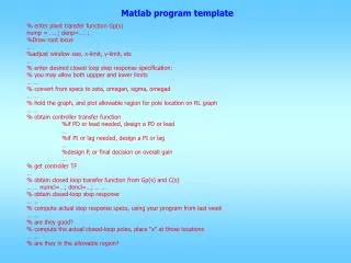
MatLAB program • User must enter values for R, C, and f of voltage source • Calculate t and T • Perform piecewise calculation • Calculate the voltage and current of the capacitor as it charges (time, t = 0s to 0.5T) • Then calculate the voltage and current of the capacitor as it discharges (time, t = 0.5T to T) • Plot the voltage and current through the capacitor for 3 periods
Enter Data • To obtain information from the program use • A= input (‘Message to user’,); • Where A is the name of the variable
Scalar vs. Vector • Scalar number is a single quantity • X = 3 • X is a scalar quantity • Vector is a string of numbers • Y = [9 12 15] • Y is a vector where the first element is 9, the second is 12, and the third element is 15 • Z=[3:-1:1] • Z is a vector where the first element is 3, the second is 2, and the third element is 1
Mathematical Operations • Scalar mathematical operations • normal *, +, -, / signs • The result of 5*X is 15 • The result of Y/X is 3 4 5 • Vector operations • +, -, .*, and ./ • The result of Z.*Y is 27 24 15 • The multiplication of the first element of Z with the first element of Y, then the multiplication of the second element of Z with the second element of Y, and finally the multiplication of the third element of Z with the third element of Y • The lengths (or number of elements) of the two vectors must be equal
If Function • The ifstatement evaluates a logical expression and executes a group of statements when the expression is true. • The optional elseif and else keywords provide for the execution of alternate groups of statements when the first statement is false. • An end keyword, which matches the if, terminates the last group of statements. • The groups of statements are delineated by the four keywords—no braces or brackets are involved.
FOR Function • The for loop repeats a group of statements a fixed, predetermined number of times. • A matching end completes the for loop.
Example 3 if X >= 3% if X is greater than or equal to 3, Y = Y+Z% the next statement is performed else Y = Y-Z % otherwise this statement is performed end Since X = 3, the result is Y = 12 14 16
Example 4 if X==2 % if X equals 2, the next statement is performed Y=Y.*Z % if not, the next statements are checked elseif X > 3% if X is >3, next statement is performed Y = Y + Z else Y = Y - Z% otherwise, this calculation is performed end Since X = 3, the result is Y = 6 10 14
Example 5 for i=1:2 % two loops through the next statement Y=Y.*Z % multiplication of the 2 vectors defined End The result is: Y = 27 24 15 at end of the 1st time throughtheloop Y = 81 48 15 at end of the 2nd time throughtheloop
Plotting Functions plot(Y) graphs the columns of Y versus the element number (index) plot(Y,Z); % Y is the x-axis & Z is the y-axis title('Z vs Y') %Inserts a title on the plot xlabel('Z (time)'); %Inserts a x-axis label on the plot ylabel('Y(volts)');%Inserts a label for the y-axis grid on % Causes a grid to appear on the plot
MatLAB Program Assignment • Plot a graph of vC(t) given by Eqs (2) and (3) versus t • for the time constant calculated from the resistor and capacitor values entered by the user* • And a voltage source cycles between 0V and 5V with a period of 1ms and 50% duty cycle • Also show the clock signal on the same graph. • Plot a graph of iC(t) versus tusing Eqs (5) and (6), for the time constant calculated in step 1. • Plot a graph of vC(t) using Eqs (7) and (8). • Equations are listed in Experiment 15 of the lab manual • All plots should show three full clock periods. • All plots should also include a plot of the clock signal on the same graph. * Note: This is different from the lab manual instructions.