Fast High Current Thyristor SEB test
Fast High Current Thyristor SEB test. Viliam Senaj, TE/ABT/FPS RAGWG meeting 18/01/2011. FHCT SEB test. Motivation SEB failure rate estimation Test arrangement Preliminary results. Motivation.

Fast High Current Thyristor SEB test
E N D
Presentation Transcript
Fast High Current Thyristor SEB test Viliam Senaj, TE/ABT/FPS RAGWG meeting 18/01/2011
FHCT SEB test • Motivation • SEB failure rate estimation • Test arrangement • Preliminary results
Motivation • LHC beam extraction generators (MKD) and sweeper of extracted beam over dump block surface (MKB) use stack of 10 FHCTs is series with maximum applied voltage up to 29.2 kV at 7 TeV (more than 2.95 kV per device due to voltage sharing accuracy); • Generators are installed in UA63 and UA67 and are supposed to see certain level of radiation (not expected in time of design); • FHCT producers (Dynex & ABB) estimate SEB failure rate due to cosmic rays (at sea level) to be10-7 device hours at 2.8 kV (100 FIT); devices are custom modified and no in field statistics is available; 700 FHCTs are installed (x 200 days x 20 hours= 2.8x10⁶ device hours per year); accurate FIT at 2.95 kV for the radiation expected in UA areas is unknown; • Failure of a FHCT will provoke asynchronous dump (beam loses) and machine down time for generator replacement (more than one day due to need of re-calibration);
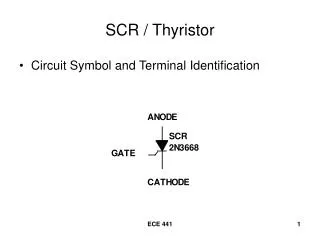
FHCT used • ABB - 5STH20H4502 • DYNEX - DG648BH45-185 • Umax: 4.5 kV • Udc: 2.8 kV (100FIT) • Imax: 80 kA • dI/dt: 20 kA/µs • Ileak: 10 µA @3kV • Load integral 8.105 A2s • Wafer diameter ~ 60 mm
SEB failure rate estimation • ABB simulation of a cosmic rays induced SEB FIT for similarly rated IGCT; • Rating of the used components is 100 FIT at 2.8 kV; we can expect up to 2.95 kV on component (voltage sharing accuracy); • According to the ABB simulation, 150 volts above 100 FIT corresponds to ~ 1500 FIT (15 x more); • 1500 FIT for 700 components and 4000 hours per year gives more than 4 SEB per year which is non-acceptable; more accurate measurement of FIT at 2.9 kV will reveal if we need to add eg. 2 more components in series to reduce applied voltage and hence corresponding FIT rate.
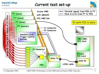
Preliminary results • Measurements done for 5 FHCT of each family (DYNEX & ABB) with 4 kV applied and with current limitattion to 650 mA and with fast acting fuse 65 mA (time to broke ~500 µs); • According to the ABB simulation, SEB failure rate at 4 kV due to cosmic rays can be estimated to ~3.105 FIT and hence MTBF should be ~300 device hours. • FHCT protection found to be not good enough so only 156 h of test was done (780 device hours for each family) with the following results: • ABB: 1 SEB • Dynex: 3 SEB • The current limitation and fast acting fuse helped to protect the FHCT from total damage, newertheless I2t was most likely too high and leaded to certain level of semiconductor deterioration – increase of a leakage current by more than 1 order of magnitude. New active protection with lower current and faster response is under construction