Download
1 / 73
760 likes | 1.04k Vues
Fusion-Welding and Solid State Welding Processes Team 6: Christopher Chavez Steve De La Torre David Jaw Matthew Witkowski November 23, 2005 ME260L. Topics:. General Safety General Welding OxyFuel Welding Arc Welding Solid-State Welding Processes Electron-beam Welding (EBW)

E N D
Fusion-Welding and Solid State Welding Processes Team 6: Christopher Chavez Steve De La Torre David Jaw Matthew Witkowski November 23, 2005 ME260L
Topics: • General Safety • General Welding • OxyFuel Welding • Arc Welding • Solid-State Welding Processes • Electron-beam Welding (EBW) • Oxyfuel Cutting • Arc Cutting • Resistance Welding
General Welding Safety: • Every year approximately 500K Welding Accidents occur • Occupational Safety & Health Administration (OSHA) • Standard 1910 Welding, Cutting and Brazing • Installation of equipment • Environmental Controls • Exposure Limits (Fumes, Vapor, and Time) • Operation and Maintenance • Common Accidents • Flash and Retinal Burns • Vapor Hazards • Electric Shock • Fires or Flammable accidents
General Welding Safety: • Personal Protective Equipment (PPE) • Welder is properly grounded • Adequate ventilation • Work in a Firesafe zone • First-Aid kit
General Characteristics of Fusion Welding Processes: • Process Description • Welding is the process by which 2 metal parts are joined by melting the parts (application of heat) at the points of contact. Most frequently used methods are Oxy-Fuel and Electric Arc welding. • There are more than 80 different types of welding operation in commercial use.
OxyFuel or OxyAcetylene Gas Welding: • OxyFuel Gas Welding is a term used to describe any welding process that uses a fuel gas with Oxygen. • The oxy-acetylene flame is made by mixing oxygen and acetylene gases in a special welding torch or blowpipe, producing, when burned, a heat of 6,300 degrees, which is more than twice the melting temperature of the common metals. • Oxygen and acetylene (typically), to produce the flames. • Filler Metals which may be added to the joints while molten in order to give the weld sufficient strength and proper form • Chemical powders, called fluxes, which assist in the flow of metal and in doing away with many of the impurities and other objectionable features.
OxyFuel Gas Welding: • Torch Practice. The actual work of welding and cutting requires preliminary preparation in the form of heat treatment for the metals, including preheating, annealing and tempering • Oxygen, the gas which supports the rapid combustion of the acetylene in the torch flame, is one of the elements of the air. • The equipment used for oxyacetylene welding consists of a source of oxygen and a source of acetylene from a portable or stationary outfit, along with a cutting attachment or a separate cutting torch.
OxyFuel Gas Welding: • This apparatus used in gas welding consists basically of a torch, two pressure regulators and twin flexible hoses. • The regulators are attached to the fuel and to the oxygen sources. The regulators are attached to the tanks and drops the pressure from about 21000 kPa (3000 lbf/in² = 200 atm) to a lower pressure for the torch.
OxyFuel Gas Welding: • General view of and • Cross-section of a torch used in oxyacetylene welding. The acetylene valve is opened first; the gas is lit with a spark lighter or a pilot light; then the oxygen valve is opened and the flame adjusted. • Basic equipment used in oxyfuel-gas welding. all threads on acetylene fittings are left-handed, whereas those for oxygen are right-handed. Oxygen regulators are usually painted green, acetylene regulators red.
OxyFuel Gas Welding: • Filler Metals • Filler rods or Wire, Copper alloy filler rods and fluxes enable the joining of many • base metals. They are especially useful on • steel and cast iron. • Flux • The flux is to retard oxidation of the surface of the parts being welding by generating a gaseous shield
OxyFuel Gas Welding: • Flames • Neutral flame • Welding is generally carried out using the neutral flame setting which has equal quantities of oxygen and acetylene. • Oxidizing Flame • The oxidising flame is obtained by increasing just the oxygen flow rate • Carburizing Flame • The carburising flame is achieved by increasing acetylene flow in relation to oxygen flow.
Arc Welding Process: • The term arc welding applies to a large and varied group of processes that use an electric arc as the source of heat to melt and join metals. In arc welding processes, the joining of metals, or weld, is produced by the extreme heat of an electric arc drawn between an electrode and the workpiece, or between two electrodes. • Metal Electrodes. In bare metal-arc welding, the arc is drawn between a bare or lightly coated consumable electrode and the workpiece. Filler metal is obtained from the electrode.
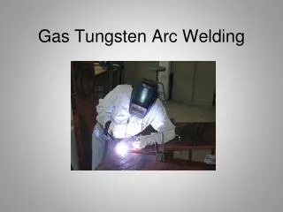
Arc Welding Process: • Various Types of Arc Welding • Nonconsumable-electrode or Gas Tungsten Arc • GTAW or tungsten inert gas (TIG) welding, is a manual welding process that uses a non-consumable electrode made of tungsten, an inert or semi-inert gas mixture, and a separate filler material. Especially useful for welding thin materials such as Stainless Steel and light metals. • Used on Bicycle, aircraft and naval applications. • Plasma Arc • PAW is an extension of the GTAW process. The arc is formed between an electrode (which is usually but not always made of a sintered tungsten) and the workpiece. The key difference from GTAW is that in PAW, by positioning the electrode within the body of the torch, the plasma arc can be separated from the shielding gas envelope.
Arc Welding Process: • Gas Tungsten Arc The gas tungsten-arc welding process, formerly known as TIG (for tungsten inert gas) welding. Equipment for gas tungsten-arc welding operations. Source: American Welding Society.
Arc Welding Process: • Plasma Arc Two types of plasma-arc welding processes: (a) transferred, (b) nontransferred. Deep and narrow welds can be made by this process at high welding speeds.
Arc Welding Process: • Electrodes for Arc Welding • Electrodes are identified by numbers and letters or by color code • Dimensions are in the range of 6 to 8 inches in length 1/16 to 5/16 in diameter. • Classified by strength, current and type of coating. • www.AWS.org • A free information web site on any and all welding processes, procedures, equipments etc…
Arc Welding Process: • Shielding Metal Arc • The arc is drawn between a covered consumable metal electrode and workpiece. • The electrode covering is a source of arc stabilizers, gases to exclude air, metals to alloy the weld, and slags to support and protect the weld. • Shielding is obtained from the decomposition of the electrode covering. • Pressure is not used and filler metal is obtained from the electrode. • Shielded metal arc welding electrodes are available to weld carbon and low alloy steels; stainless steels; cast iron; aluminum, copper, and nickel, and their alloys
Arc Welding Process: • Shielding Metal Arc Schematic illustration of the shielded metal-arc welding process. About 50% of all large-scale industrial welding operations use this process. Schematic illustration of the shielded metal-arc welding operations (also known as stick welding, because the electrode is in the shape of a stick).
Arc Welding Process: • Gas Metal Arc • In this process, coalescence is produced by heating metals with an arc between a continuous filler metal (consumable) electrode and the workpiece. • The arc, electrode tip and molten weld metal are shielded from the atmosphere by a gas. • Shielding is obtained entirely from an externally supplied inert gas, gas mixture, or a mixture o f a gas and a flux. • The electrode wire for MIG welding is continuously fed into the arc and deposited as weld metal. • Wire diameters 0.05 to 0.06 in. (0.13 to 0.15 cm) are average. Because of the small sizes of the electrode and high currents used in MIG welding, the melting rates of the electrodes are very high. • All commercially important metals such as carbon steel, stainless steel, aluminum, and copper can be welded with this process in all positions by choosing the appropriate shielding gas, electrode, and welding conditions.
Arc Welding Process: • Submerged-Arc • Basically, in submerged arc welding, the end of a continuous bare wire electrode is inserted into a mound of flux that covers the area or joint to be welded. An arc is initiated, causing the base metal, electrode, and flux in the immediate vicinity to melt. The electrode is advanced in the direction of welding and mechanically fed into the arc, while flux is steadily added. The melted base metal and filler metal flow together to form a molten pool in the joint. At the same time, the melted flux floats to the surface to form a protective slag cover.
Arc Welding Process: • Submerged-Arc Schematic illustration of the submerged-arc welding process and equipment. The unfused flux is recovered and reused. Source: American Welding Society.
Electron-beam Welding (EBW) -heat generated by high velocity narrow-beam electrons -the kinetic energy of the electrons is converted into heat
Almost any metal can be welded by this process • Depth-to-width ratios range between 10 and 30 • Distortion and shrinkage are minimal • Weld quality is good and of very high purity
Laser-beam Welding (LBW) • High-power laser beam as the source of heat which produces a fusion weld • Deep-penetrating capability
Laser beam is pulsed for spot welding thin materials • Continuous laser beam is used for deep welds on thick materials
Advantages of LBW over EBW • A vacuum is not required • Process is easier because laser beams can be shaped and manipulated • Do not generate x-rays • Quality is better: less tendency for incomplete fusion, porosity, and distortion
Cutting Oxyfuel-gas and Arc Cutting
Oxyfuel-gas Cutting (OFC) • The heat source is used to remove material instead of weld it • Preheat the workpiece with fuel gas • The higher the carbon content of the steel, the higher the preheating temperature • Cutting takes place after the oxidation (burning) of the steel
Underwater Cutting • Torches create a blanket of compressed air between the flame and the surrounding water
Arc Cutting • Air carbon-arc cutting (CAC-A) • A carbon electrode is used, and the molten metal is blown away by a high-velocity air jet
Plasma-arc cutting (PAC) -Produces the highest temperatures -used for rapid cutting of nonferrous and stainless-steel plates
3 distinct zones in a weld joint 1. Base metal 2. Heat-affected zone 3. Weld metal
Heat-affected zone (HAZ) • Within the base metal • The properties and microstructure of the HAZ depend on the rate of heat input and cooling and the temperature to which this zone was raised
Weld Quality • Porosity • Caused by gases released during melting of the weld area but trapped during solidification • Chemical reactions during welding • Contaminants
Slag Inclusions • Compounds such as oxides, fluxes, and electrode-coating materials trapped in the weld zone
Incomplete fusion and penetration • Incomplete fusion produces poor weld beads • Incomplete penetration occurs when the depth of the welded joint is insufficient
Cracks • Types of cracks: longitudinal, transverse, crater, underbead, and toe cracks
Lamellar Tears develop because of shrinkage of the restrained components of the structure during cooling • Residual Stresses caused by expansion and contraction of the weld area during heating and cooling
Weld Testing • Destructive testing • Tension test: longitudinal and transverse tension tests are performed on specimens removed from actual welded joints • Tension-shear test: used so the shear strength of the weld metal and the location of fracture can be determined • Bend Test: determines the ductility and strength of welded joints • Fracture toughness test: use impact testing techniques
Non-destructive testing techniques -Visual -Radiographic (x-rays) -Magnetic-particle -Liquid-penetrant -Ultrasonic Used instead of destructive for critical applications where weld failure can be catastrophic
Joint Design and Process Selection Select a type of weld and joint that is most practical for your application