Introduction to Gas-solid Fluidized Bed Reactors
CHEMICAL REACTION ENGINEERING LABORATORY. Introduction to Gas-solid Fluidized Bed Reactors. Professor M. H. Al-Dahhan. CHEMICAL REACTION ENGINEERING LABORATORY. Outline/Contents. Introduction. Fluidization Flow Regimes. Overall Gas (Voidage) and solids Hold-up.

Introduction to Gas-solid Fluidized Bed Reactors
E N D
Presentation Transcript
CHEMICAL REACTION ENGINEERING LABORATORY Introduction to Gas-solid Fluidized Bed Reactors Professor M. H. Al-Dahhan
CHEMICAL REACTION ENGINEERING LABORATORY Outline/Contents • Introduction. • Fluidization Flow Regimes. • Overall Gas (Voidage) and solids Hold-up. • Radial and Axial Solids Hold-Up Profiles. • Radial and Axial voidage distribution. • Gas and Solid Mixing. • Scale-Up. • Reactor Modeling.
CHEMICAL REACTION ENGINEERING LABORATORY INTRODUCTION
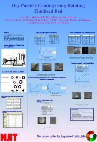
CHEMICAL REACTION ENGINEERING LABORATORY Fluidized Bed Reactor Components Inlet to cyclone The material fluidized is a solid (catalyst). The fluidizing medium is either a gas or a liquid. Gas distributor
CHEMICAL REACTION ENGINEERING LABORATORY AdvantagesDisadvantages • Broad residence time distribution of the gas due to dispersion and bypass in the form of bubbles. • Broad residence time distribution of solids due to intense solids mixing. • Erosion of internals. • Attrition of catalyst particles. • Difficult Scale-up due to complex hydrodynamics. • It has the ability to process large volumes of fluid. • Excellent gas-solid contacting. • Heat and mass transfer rates between gas and particles are high when compared with other modes of contacting. • No hot spot even with highly exothermal reaction. • Ease of solids handling.
CHEMICAL REACTION ENGINEERING LABORATORY Industrial Applications of Fluidized Bed Reactor Yang 2003 • Acrylonitrile by the Sohio Process. • Fischer-Tropsch Synthesis. • Phthalic anhydride synthesis. • Methanol to gasoline and olefin processes. • Cracking of Hydrocarbons (Fluid Catalytic Cracking, etc). • Coal combustion. • Coal gasification • Cement clinker production. • Titanium dioxide production. • Calcination of AL(OH)3. • Granulation drying of yeast. • Heat exchange • Absorption • Nuclear energy (Uranium processing, nuclear fuel fabrication, reprocessing of fuel and waste disposal).
CHEMICAL REACTION ENGINEERING LABORATORY Fluidization Flow Regimes
Geldart's Classic Classification of Powders Kunii and Levenspiel (1991) • Group A (Aeratable) :- (e.g., Ammoxidation of propylene) small mean particle size and/or low particle density (<~1.4 g/cm3), gas bubbles appear at minimum bubbling velocity (Umb). • Group B (Sand-Like) :- (e.g.,Starch) particle size 40 μm to 500 μmand density 1.4 to 4 g/cm3, gas bubbles appear at the minimum fluidization velocity (Umb). • Group C (Cohesive) :- very fine particle, particle size < 30 μm, difficult to fluidize because inter-particle forces are relatively large, compared to those resulting from the action of gas. • Group D (Spoutable) :- (e.g., Roasting coffee beans) large particle, stable spouted beds can be easily formed in this group of powders. Diagram of the Geldart classification of particles, Geldart (1973 ).
CHEMICAL REACTION ENGINEERING LABORATORY Flow Regimes in Fluidized Beds J. Ruud van Ommen, 2003
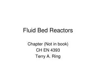
Minimum Fluidization Velocity This equation can be used to calculate the minimum fluidization velocity U if the void fraction emf at incipient fluidization is known. Experimentally, the most common method of measurement requires that pressure drop across the bed be recorded as the superficial velocity is increased stepwise through Umf and beyond, Umf is then taken at the intersection of the straight lines corresponding to the fixed bed and fluidized bed portions of the graph obtained when is plotted against U on log-log coordinates. Kunii and Levenspiel (1991)
CHEMICAL REACTION ENGINEERING LABORATORY Bubbling Fluidization • This type of fluidization has been called ‘aggregative fluidization’, and under these conditions, the bed appears to be divided into two phases, the bubble phase and the emulsion phase. • The bubbles appear to be very similar to gas bubbles formed in a liquid and they behave in a similar manner. The bubbles coalesce as they rise through the bed.
CHEMICAL REACTION ENGINEERING LABORATORY Turbulent Fluidization Turbulent regime has the following features:- • High solid hold-ups (typically 25-35 % by volume). • Limited axial mixing of gas. • Suitable for exothermic and fast reactions. • Good gas-solid contact and hence, favors reactant conversion. • high gas flow-rates operation and good for isothermal operation. • Favorable bed to surface heat transfer. Canada et al. 1978
CHEMICAL REACTION ENGINEERING LABORATORY Some commercial processes in turbulent fluidization Bi et al. 2000
CHEMICAL REACTION ENGINEERING LABORATORY Fast Fluidized Bed • The fast fluidization occurs as a result of continuing increasing in operating velocity beyond that required at turbulent fluidization, a critical velocity, commonly called the transport velocity (Utr), will be reached where a significant particle entrainment occurs. • The CFB has significant industrial applications because of its efficiency, operational flexibility, and overall profitability (Berruti et al., 1995).
Transition between Fluidization Regimes. • Grace (1986a) summarized the effects of particles properties and operating conditions on fluidization behavior and prepared a flow regime diagram. The flow regime diagram was further modified by Kunii and Levenspiel (1997). • For given particles and operating velocity, the gas-solid contact pattern can be determined using this diagram. Likewise, for a given flow regime, this diagram could provide available combinations of particle properties and gas velocity. Yang 2003
Fluidization diagram Solid hold-up Yerushalmi and Cankurt, 1970
CHEMICAL REACTION ENGINEERING LABORATORY Methods for Regime Transition Identification Several measurement methods have been utilized to determine the transition from bubbling or slugging to turbulent fluidization which can be classified into three groups:- • Visual Observation,. • Pressure Drop-versus Velocity diagram. • local and overall bed expansion. • Based on signals from pressure transducers, capacitance probes, optical fiber probes, X-ray facilities. Bi et al. 2000
Generalized effect of operating and design parameters on flow regime transition
CHEMICAL REACTION ENGINEERING LABORATORY Effect of column diameter Cai (1989) • Uc decreases with increasing column diameter for small columns (less than 2 m), becoming insensitive to column diameter for Dt> 0.2 m. • Similar trends were observed by Zhao and Yang (1991) in columns with internals.
CHEMICAL REACTION ENGINEERING LABORATORY Some Selected References • Cai et al., 1989, “Effect of operating temperature and pressure on the transition from bubbling to turbulent fluidization”, AICHE Symposium series, 85, 37-43. • Chehbouni et al., (1994), “Characterization of the flow transition between bubbling and turbulent fluidization”, Ind. Eng. Chem. Res., 33, 1889-1896. • Bi et al., (2000), “A state-of-art review of gas-solid turbulent fluidization”, Chemical engineering science, 55, 4789-4825. • Andreux et al. (2005), “New description of fluidization regimes”, AICHE Journal, 51, No.4, 1125-1130.
CHEMICAL REACTION ENGINEERING LABORATORY OVERALL GAS (VOIDAGE) AND SOLID HOLDUP
Overall gas holdupIt is an important hydrodynamic parameter which is defined as the fraction of reactor dynamic volume occupied by the gas. Typical relationship between overall gas (voidage) holdup and superficial gas velocity in where is shown in following schematic Avidan and Yerushalmi, 1970
Hilal et al. 2002 Effect of column diameter • The bed expansion increases with increasing bed diameter (Volk et al. 1962, Xavier et al., 1978). • The bed expansion decreases with increasing beds, a condition he attributed to the development of bubble channeling in the larger beds (De-Groot 1967). • The bed density is greatest for the smaller diameter bed at the same excess velocity (Hilal et al., 2002). Matsen 1996
Effect of pressure • Higher operating pressures reduced the bed expansion (H/Hmf) (Miller et al., 1981) . • The increase of bed expansion with pressure (Chiba et al., 1986, and Chitester et al., 1984) . • The physical properties of the fluidizing gas, density and viscosity did not have any significant effect on bed expansion (Denloye, 1982), and Knowlton,1977). • Bed expansion increased significantly with pressure but this influence, very strong at low pressures, seemed to reach a maximum at approximately 800kPa and decreased thereafter up to 1200kPa (Llop et al., 1995; 2000, and Olowson and Almstedt, 1990) . Some conflict !!!!!!!!!
CHEMICAL REACTION ENGINEERING LABORATORY Some Selected References • Avida and Yerushalmi (1982), “Bed expansion in high velocity fluidization”, Powder technology, 32, 223-232. • Meller et al., (1984), “The effect of particle density on the hold-up in a fast fluid bed”, AICHE Symposium series, No.234, 80, 52-59. • Lee and Kim (1990), “Bed expansion characteristics and transition velocity in turbulent fluidized beds”, 62, 207-215. • Hilal et al., (2002), “Solid hold-up in gas fluidized beds”, Chemical engineering and processing, 41, 373-379.
CHEMICAL REACTION ENGINEERING LABORATORY Radial and Axial Solids Hold-Up Profiles
CHEMICAL REACTION ENGINEERING LABORATORY Radial Profile Mabrouk et al. 2005 • Although, overall gas holdup has been traditionally used for characterization of hydrodynamics of fluidized bed columns, it is a single lumped parameter. Hence, for detailed characterization, one need to look at the way solid is distributed across the reactor. • The local solid holdup was greater near the wall compared to that near the centerline and that the radial particle velocity was nearly parabolic (Van Zoonen, 1962; Mabrouk et al. 2005). U=0.53 m/s, sand particle (250 microns, 2.5 g/cm^3)Bubbling regime, Fiber optical needle probe
CHEMICAL REACTION ENGINEERING LABORATORY Axial Profile The axial solid hold-up obtained by fiber optical needle probe and CARPT shows a quasi linear profile (Mabrouk et al. 2005). Mabrouk et al. 2005
CHEMICAL REACTION ENGINEERING LABORATORY Measurement techniques of Radial and Axial Solids Hold-Up Profile CARPT Mabrouk et al. 2005
CHEMICAL REACTION ENGINEERING LABORATORY Some Selected References • Bi et al., (2000), “A state-of-art review of gas-solid turbulent fluidization”, Chemical engineering science, 55, 4789-4825. • Mabrouk et al., “Scale effects on fluidized bed hydrodynamics” Inter. J. of Chemical Reactor Eng, 2005. • Schweitzer et al., (2001), “Local gas hold-up measurement in fluidized bed and slurry bubble column.
CHEMICAL REACTION ENGINEERING LABORATORY Gas and Solid Mixing
CHEMICAL REACTION ENGINEERING LABORATORY (a) Axial Solid Mixing Lee and Kim 1990 Du et al. 2002
CHEMICAL REACTION ENGINEERING LABORATORY (b) Radial Solid Mixing Du et al. 2002
CHEMICAL REACTION ENGINEERING LABORATORY Gas Mixing (a) Axial Gas Mixing Foka et al. 1996
(b) Radial Gas Mixing For turbulent fluidized beds, almost all gas mixing studies have been concentrated on the axial mixing, very limited information is available regarding the radial gas mixing (Du et al. 2002). Du et al. 2002 Lee and Kim 1989
Solids flow pattern and mixing Radioactive particle tracking technique for solids mixing investigations Mostoufi and Chaouki, 2001 152 mm ID, 1500 mm in height Experimental setup and the used detectors configuration
Radioactive particle tracking selected results Mostoufi and Chaouki, 2001
Solids diffusivities Mostoufi and Chaouki, 2001
Velocity field, velocity gradient and axial solid diffusivity Mostoufi and Chaouki, 2001
CHEMICAL REACTION ENGINEERING LABORATORY Some Selected References • Lee and Kim (1989), “Gas mixing in slugging and turbulent fluidized beds”, Chem. Eng. Comm., 86, 91-111. • Foka et al., (1996), “Gas phase hydrodynamics of a gas-solid turbulent fluidized bed reactor”, Chemical engineering science, No.5, 51, 713-723. • Du, B., Fan, L.-S., Wei, Fan, Warsito, W., “Gas and solids mixing in a turbulent fluidized bed”, AIChE Journal, 48, No.9, 1896-1909.
CHEMICAL REACTION ENGINEERING LABORATORY Fluidized Bed Scale-up
CHEMICAL REACTION ENGINEERING LABORATORY Scale-up criteria Sanderson and Rhodes, 2005 Glicksman et al, 1993, 1998 Horio et al., 1986 van den Bleek and Schouten, 1996
Sanderson and Rhodes, 2005 Properties of the Silica Sand Bed Materials Used in the Similarity Experiments Vertical distance from top surface of distributor plate to each pressure tapping point. The tapping point heights correspond to the same dimensionless probe height (h/Hs) at each scale.
CHEMICAL REACTION ENGINEERING LABORATORY Scale-up criteria evaluation in small scale fluidized beds Results for the average absolute deviation of dimensionless pressure for correct and misscaled beds. Materials A and B in the 146- and 300-mm beds, respectively, are correctly scaled. Materials A* and B* in the 146- and 300-mm beds, respectively, are also correctly scaled, but different from the A–B pair. Comparison of the dimensionless average cycle frequency for the pressure fluctuation data for all preliminary experiments. Sanderson and Rhodes, 2005
CHEMICAL REACTION ENGINEERING LABORATORY Scale-up criteria evaluation in large scale fluidized beds Ranges of Superficial and Dimensionless Superficial Gas Velocities and Particle Reynolds Number for the Hydrodynamic Similarity Experiments* Comparison of the normalized ensemble-averaged amplitude spectra for the dimensionless pressure fluctuations from the 146-mm bed with material A and the 300-mm bed with mismatched bed material B* at low gas velocity. Sanderson and Rhodes, 2005
CHEMICAL REACTION ENGINEERING LABORATORY Sanderson and Rhodes, 2005 Comparison of the dimensionless average absolute deviation of pressure measured from pressure probes located at h/Hs=0.77 and r/R=0 in all five fluidized beds for a range of dimensionless gas velocities. All beds, with the exception of the 600-mm bed with material D, have been scaled using the simplified scaling criteria. Comparison of the dimensionless average cycle frequency of pressure measured from pressure probes located at h/Hs=0.46 and r/R =0 in all five fluidized beds for a range of dimensionless gas velocities. All beds, with the exception of the 600-mm bed with material D, have been scaled using the simplified scaling criteria.
CHEMICAL REACTION ENGINEERING LABORATORY Sanderson and Rhodes, 2005 Agreement map showing qualitatively how well the pressure fluctuations from the various probe locations and superficial gas velocities from 1.25 to 3.5Umf match for the scaled fluidized beds. Black dots indicate the location of the probe tips in the actual measurement runs; the results have been extended across the bed width assuming the behavior to be axisymmetric (excellent agreement trends are indistinguishable; good agreement trends are similar with some scatter; poor agreement trends are only marginally better than for the misscaled scenario).
CHEMICAL REACTION ENGINEERING LABORATORY Sanderson and Rhodes, 2005 Comparison of the normalized probability distributions for the correctly scaled beds (300 mm, material B; 1560 mm, material D) with the mismatched bed (600 mm, material D) at low gas velocity for the probe located at r/R=0 and h/H=0.2. Comparison of the normalized probability distributions for the correctly scaled beds (146 mm, material A; 300 mm, material B; 1560 mm, material D) at high gas velocity for the probe located at r/R=0 and h/H=0.77.