CMS Infrastructures Issues
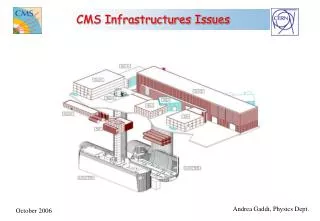
CMS Infrastructures Issues. Basic Detector Infrastructures. Definition of <Detector Infrastructures> is wide, ranging from very basic services to more detector specific systems. We give here some highlights on design guidelines and main parameters of CMS Infrastructures,

CMS Infrastructures Issues
E N D
Presentation Transcript
Basic Detector Infrastructures Definition of <Detector Infrastructures> is wide, ranging from very basic services to more detector specific systems. We give here some highlights on design guidelines and main parameters of CMS Infrastructures, focusing in particular on: Powering Cooling Cabling Safety issues Access facilities
Detector Powering • Different power utilities: • Power to Front End Electronics (FEE) • Power to Counting Rooms and Site Control Centres • Power to auxiliaries & services • Different power sources: • Uninterruptible Power (battery back-up) • Secured Power (diesel-generator back-up) • Non-secured Power
How much power System Installed power (kVA) Rated power (kW) General services on site 5,250 2,200 Electronics racks 4,000 2,300 LV to FEE 2,000 1,000 Magnet + Cryogenics 3,300 800 (1,250)* Ventilation stations (inc. smoke extraction) 5,850 1,250 (3,000)* Surface cooling stations 6,500 4,000 Underground cooling stations: 2,000 (water) 600 (C6F14) 600 (900)* Total 28,900 12,750 (15,250)* (*) refers to transient operations (cooling down, powering up, etc.)
Low Voltage Power Courtesy S. Lusin Schematics of LV distribution
Power Losses Consider a factor 2 wrt final end user to design transformers and power lines Courtesy S. Lusin
Detector Cooling Front End Electronics Cooling Electronics Racks Cooling Caverns Ventilation Cryogenics
FEE Cooling at CMS More than 1 MWatt is dissipated into heat by CMS Front Electronics boards. This large amount of heat needs to be transferred away from the Detector via appropriate cooling fluids (water or CxFy, depending on working temperature). CMS has 6 independents cooling loops, serving the following systems: Muon Endcaps water 16 deg 100 kWth Muon Barrel water 16 deg 50 kWth HCal + Yoke Barrel water 16 deg 60 kWth ECal water 16 deg 300 kWth Racks system water 16 deg 1600 kWth Tracker, Pixels, ES C6F14 -15/-30 deg 150 kWth
Cooling Infrastructures Chilled water at 6 deg is produced on surface and dispatched to the different cooling stations present on site (above and below ground) that finally produce water at 16 deg for the different cooling loops. This arrangement has made possible to test a significant part of CMS on surface, before lowering the Detector down into the cavern without having s large impact on infrastructure costs.
Racks Cooling Turbine unit Up to 8 kW per rack Integrated smoke detection Integrated fire-quenching Electronics crate Water manifold Axial fans Heat exchanger(s) Vertical air-flow Air-deflector
PC Racks Cooling Up to 10 kW per rack (40 PCs) rack mounted PCs air-to-water heat-exchanger fans Horizontal air-flow
Caverns Ventilation Humidity and temperature controls: keep dew point as lower as possible
Cryogenics The cryogenic plant at CMS site has the function to cool down and keep at 4,7 K the 230 tons of the CMS Superconducting Coil. The refrigerator system can deliver a cooling power of 800 W at 4,7 K, plus 4500 W at 60 K to cool the Coil thermal screens and in addition to that 4 g/sec of L-He to cool the 20 kA Coil Current Leads. Cooling the Coil down from ambient temperature takes 3 weeks, with a maximum thermal gradient inside the cold mass of 15 deg. In case of quench, the temperature rises up to 70 K and 3 days are necessary to bring the cold mass down to 4,7 K A 6,000 lt L-He storage tank sits close to the cold mass to allow a slow-discharge from full current without warming up the coil.
300 K 4 K 3 Feb 2006 25 Feb 2006 Coil cooling down
Detector Cabling Cabling an LHC detector is one of the most time consuming and challenging tasks. As cables come rather late in the construction process, little or no contingency is given to perform this task. CMS, due to its particular modularity, can be cabled by slices, making the process more flexible and repetitive. We have some 20,000 cables on the detector itself, with an average length of 15 meters. In addition, there are some 4,000 cables that connect the detector to the adjacent Counting rooms (average length 90 meters). Think big! Full-high false floor (1,80 m) below counting rooms and large cable-chains, make the cabling work a bit less painful than usual.
On-Detector Cabling Courtesy G. Faber Cable trays over the Coil cryostat on YB0
Off-Detector Cabling YE+1 and YB+2 chains under cabling
Cabling costs A few installation activities have their cost related to how your work is well organized as cabling. Manage cabling teams in terms of number of people on site, working on shift, requires perspective view. CMS has chosen to have teams coming from Institutions (Russia and China) namely for on-detector cables and place industrial contract with local cabling companies for off-detector cables. On this basis we have reached good results, keeping costs at a reasonable level. The predicted cost for Institution cabling was 2,3 CHF/meter and the actual one is 2,6 CHF/meter The cost for cabling made by local companies ranges from 3 to 3,3 CHF/meter. Total estimated cost is about 1,7 MCHF (equivalent to 300 men/month). Cabling cost is charged to sub-detectors according to the actual length of cables pulled.
Safety • Major danger for any experiment is fire • Fire prevention (rules & standards, gas inertion) • Fire detection (sniffers & gas analyzers, smoke-detectors) • Fire fighting (low pressure water, high pressure water, foam) The power density of LHC experiments is much larger than any other before: 2,6 GJ stored inside the Magnet 1 MW of FEE Low Voltage Power 10 kW per rack (…) CMS has been designed since the beginning with a great attention to prevent fire Being the result of a fire inside the experimental cavern potentially disastrous, we have tried to limit the overall risk keeping this possibility as low as possible.
Safety guidelines • Fire prevention: • - IS23 & IS41 Standards (Materials, Fire resistance, Smoke release) • - permanent N2 inertion inside vacuum tank and inner detectors Tracker, ECAL, HCAL • - all heat sources including front end electronics are intercepted by water, • -- all detectors and their services (cables trays) must be neutral thermally with respect to their neighbors. • Fire detection: • - smoke detection in counting rooms and cable labyrinths (sniffers) • - smoke detection in detectors cuts electrical power to concerned racks • and power supplies through DSS and its flexible action matrix • - smoke detection in racks with electrical cuts through DSS • and local fire suppression for valuable electronics • Fire fighting: • - N2 flushing of muon chamber gaps in case of smoke detection • - passive foam system in case of loss control of a fire in the cavern • - low pressure water sprinklers in cable trays • - high pressure water sprayer to quench fire in PC racks and control rooms
Foam test The UXC55 cavern has been filled with hundreds of cubic meters of foam, blown out of the 8 nozzles located at cavern ceiling.
Detector Safety System The Detector Safety System is a PLC (Siemens) based supervisor that gets alarms from its own sensors placed in every sensitive location. It has built inside an alarm/action matrix, that can be adapted to the evolution of the hardware to be protected and/or the level of risk. Actions are taken with a time delay ranging from a few seconds to some minutes, depending on the severity of the risk. All its connections are hardwired and it has a built-in UPS to assure power anytime. It exchanges data with the detector slow control and has a back end interface that allows the user to visualize the status of all the sensitive parts.
Rack Safety System Control touch screen to power racks on/off
Access Facilities Scaffolding For long term planned works. They assure easy and safe access at high. Personnel Access Platforms The more versatile access mean. Battery powered, can work in surface and underground areas. CMS has 6 PAC for installation and maintenance porpoises.
Conclusions Detector Infrastructures shall profit at a maximum of what already exists on the market. We have found on industrial systems solutions to most of our needs. Our goal was to adapt them to the complex needs of a high energy physics detector, rather than start from scratch with new solutions, that could seem more convenient, but they often lack in reliability. In short terms, do no reinvent the wheel!