Download
1 / 148
1.65k likes | 2.07k Vues
End-to-End Protocols. 5.1 Simple Demultiplexer (UDP) 5.2 Reliable Byte-Stream (TCP) 5.3 Remote Procedure Call (RPC) 5.4 Transport for Real-Time Applications (RTP). Underlying best-effort network drop messages reorder messages deliver duplicate copies of a given message

E N D
End-to-End Protocols 5.1 Simple Demultiplexer (UDP) 5.2 Reliable Byte-Stream (TCP) 5.3 Remote Procedure Call (RPC) 5.4 Transport for Real-Time Applications (RTP)
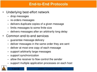
Underlying best-effort network • drop messages • reorder messages • deliver duplicate copies of a given message • limit messages to some finite size • deliver messages after an arbitrarily long delay • Transport layer protocol • support communication between the end application programs • also called “end-to-end protocol”
Dst Src Application Application Transport Transport Signals host-to-host packet delivery Network Network global addressing routing Data Link Data Link framing, error detection, reliability control, media-access control Physical Physical
Common properties that a transport protocol should provide • guarantee message delivery • deliver messages in the same order they are sent • deliver at most one copy of each message • support arbitrarily large messages • support synchronization between the sender and the receiver • allow the receiver to apply flow control to the sender • support multiple application processes on each host
5.1 Simple Demultiplexer (UDP) • Unreliable and unordered datagram service • Support multiplexing • allows multiple application processes on each host to share the network • No flow control
Endpoints identified by ports • servers have well-known ports, examples • domain name server (DNS) receives messages at well-known port 53 on each host • mail service listens for messages at port 25 • the Unix talk program accepts messages at port 517 • this mapping is published periodically in an RFC (Request for Comments) and is available on most Unix systems in file /etc/services • Internet's User Datagram Protocol (UDP) is an example of such a transport protocol
The header for an end-to-end protocol that implements this demultiplexing function typically contains an identifier (port) for both the sender (source) and the receiver (destination) of the message • For example, the UDP header UDP header format
UDP header format • UDP port field is 16 bits long • i.e., up to 64K (=216) possible ports • ports are not interpreted across the entire Internet, but only on a single host • a process is identified by a port on some particular host - a (port, host) pair • UDP header consists of only 4 fields • two of them is optional (Source Port & Checksum)
Fields • Source port • identifies the sending port when meaningful and should be assumed to be the port to reply to if needed • if not used, then it should be zero • Destination port • identifies the destination port and is required
Length (16-bit) • specifies the length in bytes of the entire datagram: header and data • the minimum length is 8 bytes since that's the length of the header • the field size sets a theoretical limit of 65,535 bytes for the data carried by a single UDP datagram • the practical limit for the data length which is imposed by the underlying IPv4 protocol is 65,507 bytes • Checksum (16-bit) • used for error-checking of the header and data
A port is purely an abstraction • exactly how it is implementeddiffers from system to system, or more precisely, from OS to OS • example, the socket API described is an example implementation of ports
A port is implemented by a message queue • when a message arrives, the protocol (e.g., UDP) appends the message to the end of the queue • should the queue be full, the message is discarded • there is noflow-control mechanism that tells the sender to slow down • when an application process wants to receive a message, one is removed from the front of the queue • if the queue is empty, the process blocks until a message becomes available
UDP computes its checksum over • UDP header • the contents of the message body • pseudoheader • Pseudoheader consists of • protocol number • source IP address • destination IP address • UDP length field
UDP uses the same checksum algorithm as IP (section 2.4.2) • Motivation behind the pseudoheader • verify this message has been delivered between the correct two endpoints • example, if the destination IP address was modified while the packet was in transit, causing the packet to be misdelivered, this fact would be detected by the UDP checksum
5.2 Reliable Byte Stream (TCP) • In contrast to a simple demultiplexing protocol like UDP, a more sophisticated transport protocol is one that offers a reliable, connection-oriented, byte-stream service • it frees the application from having to worry about missing or reordered data • Internet's Transmission Control Protocol (TCP) is probably the most widely used protocol of this type
TCP • guarantees reliable, in-order delivery of a stream of bytes • a full-duplex protocol • each TCP connection supports a pair of byte streams, one flowing in each direction • a flow-control mechanism • allows the receiver to limit how much data the sender can transmit at a given time • keep sender from overrunning receiver
a demultiplexing mechanism • allows multiple application programs on any given host to simultaneously carry on a conversation with their peers • a highly-tuned congestion-control mechanism • keep sender from overrunning network
5.2.2 Segment Format • TCP • a byte-oriented protocol, which means that the sender writes bytes into a TCP connection and the receiver reads bytes out of the TCP connection • "byte stream" describes the service TCP offers to application processes • app writes bytes • TCP sendssegments • app reads bytes
TCP does not itself transmit individual bytes over the Internet • TCP on the source host buffers enough bytes from the sending process to fill a reasonably sized packet and then sends this packet to its peer on the destination host • TCP on the destination host then empties the contents of the packet into a receive buffer, and the receiving process reads from this buffer at its leisure
Application process Application process Write Read bytes bytes TCP TCP Send buffer Receive buffer ■ ■ ■ Segment Segment Segment Transmit segments How TCP manages a byte-stream
The packets exchanged between TCP peers are called segments • Each TCP segment contains a header TCP header format
12:12:23.323832 IP 202.112.0.89.22 > 59.66.24.130.49893: P 1:41(40) ack 1 win 57920 <nop,nop,timestamp 497903510 1198492021> 0x0000: 4500 005c 0700 4000 3606 1f0f ca70 0059 E..\..@.6....p.Y 0x0010: 3b42 1882 0016 c2e5 3c1c e61f 7172 3969 ;B......<...qr9i 0x0020: 8018 e240 edb1 0000 0101 080a 1dad 6796 ...@..........g. 0x0030: 476f 8975 5353 482d 312e 3939 2d4f 7065 Go.uSSH-1.99-Ope 0x0040: 6e53 5348 5f33 2e35 7031 2046 7265 6542 nSSH_3.5p1.FreeB 0x0050: 5344 2d32 3030 3330 3230 310a SD-20030201. 32 bits Source port Destination port Sequence number Acknowledgement number TCP HL TCP headerlength UR G ACK PSH RST SYN FIN Window size Checksum Urgent point Options (0 or more 32-bit words) TCP Segment Format
SrcPort & DstPort (16-bit) • identify the source and destination ports • Sequence number • count in bytes • 32-bit unsigned • Acknowledgment number • confirm that all the previous bytes has been received • request for the byte with next sequence number • Window size • TCP’s sliding window • window size tells the sender that currently the receiver can accept how many bytes after the bytes ever confirmed
Each TCP connection identified with 4-tuple (TCP's demux key) • (SrcPort, SrcIPAddr, DsrPort, DstIPAddr) • Sliding window + flow control • Acknowledgment, SequenceNum, and AdvertisedWindow fields are involved • SequenceNum • each byte of data has a sequence number • SequenceNum field contains the sequence number for the first byte of data carried in that segment • Acknowledgment & AdvertisedWindow • carry information about the flow of data going in the other direction
Simplified illustration (showing only one direction) of the TCP process, with data flow in one direction and ACKs in the other
Flags (6-bit):SYN, FIN, RESET, PUSH, URG, ACK • used to relay control information between TCP peers • SYN & FIN • used when establishing and terminating a TCP connection, respectively • SYN:synchronize the sequence number • FIN (Finish): close the connection • ACK • set any time the Acknowledgment field is valid
URG • signifies that this segment contains urgent data • when this flag is set, the UrgPtr field indicates where the nonurgent data contained in this segment begins • the urgent data is contained at the front of the segment body, up to and including a value of UrgPtr bytes into the segment • usage: interrupt remote computation • PUSH • signifies that the sender invoked the push operation, which indicates to the receiving side of TCP that it should notify the receiving process of this fact
RESET • reset connection • signifies that the receiver has become confused • example, because it received a segment it did not expect to receive, and so wants to abort the connection
Checksum • used in exactly the same way as for UDP • Checksum is computed over • pseudo header + TCP header + TCP data
pseudo header • made up of the source address, destination address, and length fields from the IP header • TCP header • since the TCP header is of variable length, a HdrLen field is included that gives the length of the header in 32-bit words • this field is also known as the Offset field, since it measures the offset from the start of the packet to the start of the data
Options • no more than 40 bytes • most frequently used option • MSS (maximum segment size) • often carried in segments with SYN = 1
5.2.3 Connection Establishment and Termination • A TCP connection begins with a client (caller) doing an active open to a server (callee) • assuming that the server had earlier done a passive open, the two sides engage in an exchange of messages to establish the connection • only after this connection establishment phase is over do the two sides begin sending data • as soon as a participant is done sending data, it closes one direction of the connection, which causes TCP to initiate a round of connection termination messages
Three-Way Handshake • Three-way handshake • the algorithm used by TCP to establish and terminate a connection • it involves the exchange of three messages between the client and the server • idea • two parties want to agree on a set of parameters, which, in the case of opening a TCP connection, are the starting sequence numbers the two sides plan to use for their respective byte streams
parameters might be any facts that each side wants the other to know about • first, the client (the active participant) sends a segment to the server (the passive participant) stating the initialsequence number it plans to use (Flags = SYN, SequenceNum = x) • the server then responds with a single segment that both acknowledges the client's sequence number (Flags = ACK, Ack = x + 1) and states its own beginning sequence number (Flags = SYN, SequenceNum = y) • i.e., both the SYN and ACK bits are set in the Flags field of this second message
finally, the client responds with a third segment that acknowledges the server's sequence number (Flags = ACK, Ack = y + 1) • each side acknowledges a sequence number that is one larger than the one sent is that the Acknowledgment field actually identifies the "next sequence number expected," thereby implicitly acknowledging all earlier sequence numbers
Active participant Passive participant (client) (server) SYN, SequenceNum = x SYN+ACK, SequenceNum=y, Acknowledgment =x+1 ACK, Acknowledgment =y+1 Timeline for three-way handshake algorithm
State-Transition Diagram • The following diagram shows a state transition diagram • the states involved in opening a connection (everything above ESTABLISHED) and in closing a connection (everything below ESTABLISHED) • the operation of the sliding window algorithm is hidden in the ESTABLISHED state
Notations • each rectangle denotes a state that one end of a TCP connection can find itself in • all connections start in the CLOSED state • as the connection progresses, the connection moves from state to state according to the arcs • each arc is labeled with a tag of the form event/action
If a connection is in the LISTEN state and a SYN segment arrives (i.e., a segment with the SYN flag set) • the connection makes a transition to the SYN_RCVD state and takes the action of replying with an ACK + SYN segment
Two kinds of events trigger a state transition • a segment arrives from the peer (e.g., the event on the arc from LISTEN to SYN_RCVD) (peer-to-peer interface) • the local application process invokes an operation on TCP (e.g., the active open event on the arc from CLOSE to SYN_SENT) (service interface) • i.e., TCP's state-transition diagram effectively defines the semantics of both its peer-to-peer interface and its service interface
1 2 3 5 4 • Trace • when opening a connection, the server first invokes a passive openoperation on TCP, which causes TCP to move to the LISTEN state • at some later time, the client does an active open, which causes its end of the connection to send a SYN segment to the server and to move to the SYN_SENT state • when the SYN segment arrives at the server, it moves to the SYN_RCVD state and responds with a SYN + ACK segment • the arrival of this segment causes the client to move to the ESTABLISHED state and to send an ACK back to the server • when this ACK arrives, the server finally moves to the ESTABLISHED state
Three combinations of transitions that get a connection from ESTABLISHED state to CLOSED state • this side closes first • ESTABLISHED → FIN_WAIT _1 → FIN_WAIT _2 → TIME_WAIT → CLOSED • the other side closes first • ESTABLISHED → CLOSE_WAIT → LAST _ACK → CLOSED • both sides close at the same time • ESTABLISHED → FIN_WAIT _1 → CLOSING → TIME_WAIT → CLOSED
5.2.4 Sliding Window Revisited • Roles of sliding window • ensure reliable delivery of data • unacknowledged data must be buffered by sender • ensure in-order delivery of data • out-of-order data must be buffered by receiver • enforce end-to-end flow control • too fast sender should be blocked
Receiver • advertises a window size to the sender instead of being fixed (using the AdvertisedWindow field in the TCP header) • selects a suitable value for AdvertisedWindow based on the amount of memory allocated to the connection for the purpose of buffering data • Sender • limited to having no more than a value of AdvertisedWindow bytes of unacknowledged data at any given time • Idea • keep the sender from overrunning the receiver's buffer
Reliable and Ordered Delivery • TCP on the sending side • maintains a send buffer, used to store • the data that has been sent but not yet acknowledged • the data that has been written by the sending application, but not transmitted • TCP on the receiving side • maintains a receive buffer, used to hold • the data that arrives out of order • the data that is in the correct order (i.e., there are no missing bytes earlier in the stream) but the application process has not yet had the chance to read
Sending side • three pointers are maintained into the send buffer • LastByteAcked [最先產生的byte] • LastByteSent [次中產生的byte] • LastByteWritten [最後產生的byte] • Relationship • LastByteAcked [先] ≦ LastByteSent [後] • LastByteSent [先] ≦ LastByteWritten [後]
Receiving side • three pointers are maintained into the receive buffer • LastByteRead [先] • LastByteRcvd [in order 中, out of order 後] • NextByteExpected [in order 後, out of order 中(points to the start of the first gap in the data)]
Relationship • LastByteRead < NextByteExpected • a byte cannot be read by the application until it is received and all preceding bytes have also been received • NextByteExpected points to the byte immediately after the latest byte to meet this criterion • NextByteExpected ≦ LastByteRcvd +1 • if data has arrived in order, NextByteExpected points to the byte after LastByteRcvd (as the above formula shows) • if data has arrived out of order, NextByteExpected points to the start of the first gap in the data (as in the figure)