Download
1 / 18
460 likes | 1.98k Vues
Galvanometer as Ammeter/ Voltmeter. Galvanometer_diagram.svg . Using Right hand Rule Force F is developed while Flux density B from permanent magnet along with I Current passing through the coil is present:. Application of Ammeter/Voltmeter. Moving Coil Ammeter. Linear Scale due to

E N D
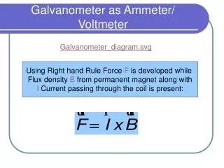
Galvanometer as Ammeter/ Voltmeter Galvanometer_diagram.svg Using Right hand Rule Force F is developed while Flux density B from permanent magnet along with I Current passing through the coil is present:
Moving Coil Ammeter Linear Scale due to Moving Coil
Moving Iron Ammeter Non-linear Scale Due to Moving Iron
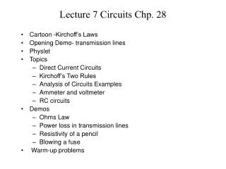
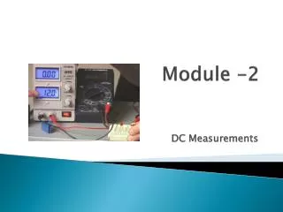
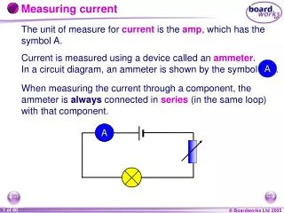
Ammeter An ammeter consists of a galvanometer with a shunt resistor. The input current iin divides with im passing through the meter and ish Passing the shunt. It is clear from Fig:
Design of Ammeter • If Rm=50 ohm and it is required that full scale capability of 1 mA is to measure up to 5 A: Rsh = 0.001*50/(5-0.001) 0.01 Ohm
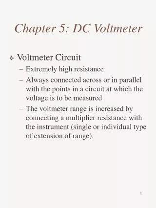
Voltmeter • Galvanometer is used as a voltmeter by connecting a series resistor Rse where current remains same but total resistance is extended to extend the scale. Vin = Vm + Vse
Design of Voltmeter • A full scale 1 mA Galvano of 50 0hm to measure 5 Volt FS: Rse = (5/0.001)- 50 = 4950 Ohms A series resistance of 4950 Ohm will enable the same to read FS 5 Volts
Electrodynamometer Wattmeter
Wattmeter • The fixed coil of the wattmeter is connected in series with the circuit (load), and the moving coil is connected across the line. When line current flows through the fixed coil of a wattmeter, a field is set up around the coil. The strength of this field is in phase with and proportional to the line current. The moving coil of the wattmeter generally has a high-resistance resistor connected in series with it. The purpose for this connection is to make the moving-coil circuit of the meter as purely resistive as possible. As a result, current in the voltage circuit is practicallyin phase withline voltage. Therefore, when voltage is impressed on the voltage circuit, current is proportional to and in phase with the line voltage. V I
Tutorials Where: Ti Torque developed due to current N No of turns of the coil carrying current Flux density created by the magnet L axial length of the coil under the pole D mean diameter of the coil I current passing through the coil Where: Tc torque developed in Control spring k stiffness constant of the spring angular deflection turned due to current While Ti = Tc Where: S sensitivity or calibration constant of the meter
Tutorial ….. • Full scale range of GALVANO is 25uA, while full deflection is 45 degree. Determine the sensitivity “S”: Therefore : S = /i S = 45/25x10-6 =40000deg/A
Assignment 1 Q.No 1: A galvano of 3 Ohm resistance reads a maximum current of 150 milliampere. How can it be used for: • A voltmeter to read upto 15 volts • An ammeter to read upto 30 ampere Q.No 2: In a voltmeter the moving coil consists of 100 turns wound on a square former has a length of 3 cm and a flux density in the air 0.06 Wb/m3. Calculate deflecting torque when the coil is carrying a current of 12 milliampere.
Strip Chart Recorder This utilizes a servomotor-driven null-balance potentiometeric circuit. Input is amplified and fed to servo amplifier to produce error signal using feedback. Servo motor poition wiper and pen across moving chart for recording signals. Feedback Reference Voltage + Printer roller Wiper & Pen drive + Zero set Chart paper _ Input signal Signal amplifier Servo amplifier Servo motor Gear Dive Reference voltage - Synchronous Motor
Typical Specifications ofChart Recorder Paper width: 120-250mm; Sensitivity: 5mV to 100V Speed: 25mm/h to 250mm/h Response Time: 0.5 seconds
Typical Applications Any time varying variable can be manipulated for record on Chart Recorders as part of overall Database; such as: • ECG • Weather Forecast • Temperature • Pressure • Humidity • Seismic History
X-Y Recorders • Working of the recorder is again based on dualservo motor-driven null-potentiometric circuits as described in Chart Recorder. • Paper is stationary rather than rolling along time. • Pen is controlled in both axes; x and y direction. • The recorder may have single or multiple pens with different colors • Many have time base available for time varying quantities.