Threading Die
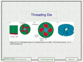
Threading Die. Figure 22.19 (a) Straight chasers for cutting threads on a lathe. (b) Circular chasers. (c) A solid threading die. Boring.

Threading Die
E N D
Presentation Transcript
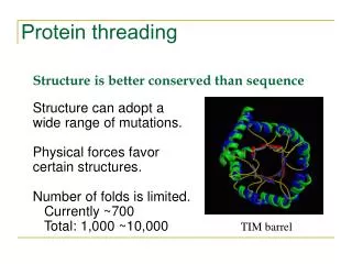
Threading Die Figure 22.19 (a) Straight chasers for cutting threads on a lathe. (b) Circular chasers. (c) A solid threading die.
Boring Figure 22.20 (a) Schematic illustration of a steel boring bar with a carbide insert. Note the passageway in the bar for cutting fluid application. (b) Schematic illustration of a boring bar with tungsten-alloy “inertia disks” sealed in the bar to counteract vibration and chatter during boring. This system is effective for boring bar length-to-diameter ratios of up to 6. (c) Schematic illustration of the components of a vertical boring mill. Source: Kennametal Inc.
Horizontal Boring Mill Figure 22.21 Horizontal boring mill. Source: Giddings and Lewis, Inc.
Drill Point Geometries Figure 22.23 (a) Standard chisel-point drill indicating various features. The function of the pair of margins is to provide a bearing surface for the drill against walls of the hole as it penetrates into the workpiece; drills with four margins (double-margin) are available for improved drill guidance and accuracy. Drills with chip-breaker features are also available. (b) Crankshaft-point drill. (c) Various drill points and their manufacturers: 1. Four-facet split point, by Komet of America. 2. SE point, by Hertel. 3. New point, by Mitsubishi Materials. 4. Hosoi point, by OSG Tap and Die. 5. Helical point.
Drilling and Reaming Operations Figure 22.24 Various types of drilling and reaming operations.
Gun Drilling Figure 22.25 (a) A gun drill showing various features. (b) Method of gun drilling. Source: Eldorado Tool and Manufacturing Corporation.
Trepanning Figure 22.26 (a) Trepanning tool. (b) Trepanning with a drill-mounted single cutter.
General Troubleshooting and Drill Life Figure 22.27 The determination of drill life by monitoring the rise in force or torque as a function of the number of holes drilled. This test is also used for determining tap life.
(a) Drilling Machines Figure 22.28 Schematic illustration of components of (a) a vertical drill press and (b) a radial drilling machine.
CNC Drilling Machine Figure 22.29 A three-axis computer numerical control drilling machine. The turret holds as much as eight different tools, such as drills, taps, and reamers.
Reamers Figure 22.30 (a) Terminology for a helical reamer. (b) Inserted-blade adjustable reamer.
Tapping and Taps Figure 22.31 (a) Terminology for a tap. (b) Tapping of steel nuts in production.