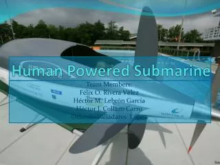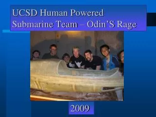
Human Powered Submarine
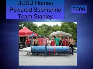
Human Powered Submarine. Introduction The submarine’s general characteristics The hull Propulsion system Fins Propeller Security system Direction system Conclusion Questions??. Introduction. The team Previous speed records Our goal. General Characteristics. One person, Propeller

Human Powered Submarine
E N D
Presentation Transcript
Introduction • The submarine’s general characteristics • The hull • Propulsion system • Fins • Propeller • Security system • Direction system • Conclusion • Questions??
Introduction • The team • Previous speed records • Our goal
General Characteristics • One person, Propeller • Modeling done with CATIA V5R19 • The hull • Smallest in volume (105 in x 20 in x 24 in)
General Characteristics • The propulsion system • Similar to Omer4 • Pedaling = rotor movement • Variable pitch added • The direction system • Four fins • Fully mechanical system
General Characteristics • The security system • Same as Omer7 • Pneumatic system with actuators • Dead man switch
The hull • Constraints • Methodology • Ergonomic test • Hydrodynamic analysis • Fabrication • Results
The hull (Constraints) • Minimum required space for pedaling • Size of the pilot • Dimensions of the constraints
The hull (Modeling) • CATIA V5R19 • NACA series 6 airfoils • Technique • Horizontal airfoils(shoulder and foot width) • Vertical airfoils(hip length and minimum length) • ellipses
The hull (Ergonomic test) • Enough space? • Sectional analysis -Knee fitting -Shoulder and tank fitting -Pedals fitting
The hull(Hydrodynamic analysis) • Computational Fluid Dynamics • Floworks by Solid works 2007 • Simulates a fluid at a speed of 4m/s • Trajectory of fluid + power of drag • Optimal results
The hull(Fabrication) • Resin infusion process • Saves time and $$
The hull(Fabrication) • Carbon fiber+ epoxy resin • Difference: carbon/innegra fiber • Nose window = polycarbonate(Lexan) • Good impact resistance+ translucent
Results • Final hull • NACA66020 for vertical plane,NACA63013 for horizontal plane
Propulsion system • Modeling • Description • Technical specifications • Variable pitch • Functionality of the variable pitch • Fabrication • Electrical system
Propulsion system(Modeling) • CATIAV5R19 • Bearings • Bevel gears • Seals • Motors • Etc.
Propulsion system(Description) 1- Plate glued to the hull 2- Structure support 3-Top cover plate 4-Driveshaft tube 5-Bottom cover plate 6-Gear box
Propulsion system(Description) 1-Pedal 2-Crank set level 3-Lateral cover plate 4-Bearing housing 5-Lateral structure 6-Button bracket 7-Big bevel gear 8-gear box case 9-Button bracket bearing 10-Small bevel gear 11-Drive shaft 12-Drive shaft bearing 13-Drive shaft tube support
Propulsion system(variable pitch) • In dependent electrical system • Holds two blades at a certain angle 1-Head cone 2-Rotor cone 3-Turning plate 4-Hub 5-Cover tube 6-Driveshaft
Propulsion system(variable pitch) 1-Electrical motor 2-Motor support 3-Head cone seal 4-motor bushing 5-Rotor cone seal 6-Propeller blade bearing 7-Battery pack 8-Bevel gears 9-Bearing 10-Water proof connector 11-Electrical board
Propulsion system(variable pitch) • Angle of the blades for best acceleration • Electrical system (pcb + code) • Magnetic switch + direct programing • Rpm = angle • Reajusting
Propulsion (fabrication) • Mostly fabricated within our facilities • Standard bicycle parts • Aluminium
Fins and propeller • Polyurethane casting • Aluminum moulds • Fabricated on CNC at 12000 RPM (4hrs) • Aluminum • Clouds of points and aeronautics airfoils
Direction • Fully mechanical • Joystick on rails + cables • Direction on joystick= Direction of sub
Safety system • Pneumatic • Dead man switch • Same air source as pilot