Download
1 / 36
370 likes | 401 Vues
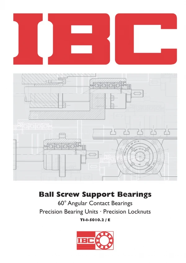
Range of IBC Precision Products for Support of Ball Screws<br><br>Fields of application of 60° super precision angular contact ball bearings and units: Rigid but fairly low-friction assembly of ball screws or satellite screws for conversion of rotary movement into linear movement (among others, also in worm gears for rotating tables or in tailstocks). To Know More Visit:http://www.carterbearings.co.uk/wp-content/themes/default/downloads/ibc/IBC_Ball_Screw_Support_Bearings.pdf

E N D
Ball Screw Support Bearings 60°Angular Contact Bearings Precision Bearing Units · Precision Locknuts TI-I-5010.2 / E
Location withTradition The headquarters in Solms-Oberbiel is centrally located in Germany close to the North/South and East/West highways which also provides fo a central location in Europe. The internationalAirport Frankfurt approx. 80 km away serves as a worldwide link. Headquarter of the IBC Wälzlager GmbH at the industrial area of Solms-Oberbiel Flexible and Reliable In the middle of 1996 we opened the central computer controlled high shelf warehouse with more than 2.000 pallet places. It is used for finsihed and semi-finished products as well as for large bearings. This is in addition to our existing two-storage computer controlled service warehouse also with more than 2.500 storage places. Both warehouse systems provide together with our distribution centre and communication network precise logistics and a worldwide unequaled reliability. Precise Logistics provide an unequaled worldwide reliability Central Computer Controlled High ShelfWarehouse – Middle 1996 Precision with Future We are future orientated. We have the creativity and vision to perform and provide. This is our exact presentation to solutions with precision.
Table of Contents Page 4 4 4 6 1. 2. 2.1 2.2 Range of IBC Precision Products for Support of Ball Screws Definition of Bearing Size Capacity and Life Time Selection of Preload, Axial Stiffness BS 7 7 8 3. 3.1 3.2 3.3 3.4 3.5 Super Precision 60° - Angular Contact Thrust Ball Bearings Designation Dimensional Tables Tolerances of Bearings Recommended Fits Tolerances of Adjacent Parts 10 10 11 12 15 16 18 20 21 22 23 24 25 4. 4.1 4.2 4.3 4.4 4.5 4.6 4.7 4.8 4.9 High Precision Bearing Units, Criteria of Selection Designation High Precision Flange Units High Precision Pillow Block Units High Precision Flange Units for Ball Screw Nuts High Precision Pillow Block Units for Ball Screw Nuts Technical Data Table High Precision Floating End Units Mounting dimensions for Ball Screw Spindles Criteria for Arrangements of Bearings at Ball Screws BSBU, BSBU-M BSPB, BSPB-M BNBU BNPB BLPB, BLBU 27 28 29 30 32 5. 5.1 5.2 5.3 5.4 Precision Accessories Precision Labyrinth Locknuts Labyrinth-Seals and Seal-Nuts Precision Locknuts Pretension of Spindles with Precision Locknuts MMRS S, MD MBA, MBAS, MMA, MMR, MMRB, MMRBS 33 34 34 34 34 6. 7. 8. 8.1 8.2 Drawings for Inquiries for Fixed End and Floating End Units Alpha-Numerical Product Directory Glossary (Materials) Material Grease IBC INDUSTRIAL BEARINGS AND COMPONENTS 3
1. Overview Precision bearing units For 20 years IBC Wälzlager GmbH has been mounting open bearings into housings with labyrinth seals. Two series for driven spindles and driven nuts have turned out to be the most effective: a) Cartridge Units with Flanged Housing b) Pillow Block Units The cartridge units with integrated labyrinth seal and life- time lubrication have been revised and designed to allow for easier mounting. The seat diameter was enlarged to be able to slide a pre-assembled module (ball screw with it’s nut + bearing unit, if applicable) through the attachment bore of the unit. This proved to be helpful for maintenance. Range of IBC Precision Products for Support of Ball Screws Fields of application of 60° super precision angular contact ball bearings and units: Rigid but fairly low-friction assembly of ball screws or satellite screws for conversion of rotary movement into linear movement (among others, also in worm gears for rotating tables or in tailstocks). In particular 60° precision angular contact ball bearings are used for machine tools or machines and devices with similar high requirements regarding precision, speed but also rigidity and a lower friction behaviour and thus a less heating up of the bearings or components. Standard models and options The units are available as standard, duplex and quadru- plex units with lifetime lubrication. The DB duplex units, which are flattened on both sides can also be provided as DT tandem unit for applications with longer spindles and a second bearing side (see page 33). The matching disc springs and spacers for preloading or a slight stretching of the spindle are part of the delivery. Quadruplex units are mainly mounted in QBC tandem-O- tandem arrangements but can also be delivered in a QBT arrangement, i.e. 3:1 stacking of the bearings (of interest for vertical axes with a preferred direction of load). If re- quired by the customer, additional attachment bores, e.g. for bellows of the ball screw or additional centring loca- tions for direct flange mounted servo motor mounts can be integrated. Advantages Of course easy assembly, a long life time, the option of lifetime lubrication or circulating oil lubrication, as sometimes employed for driven ball screw nuts are other features which should be adjusted to match each other optimally. Next to the open 60° bearings, several sizes are manufactured with a non-contact rubber seal at both ends. High axial loads Whereas contact ball bearings with small contact angles of 15°, 25° mainly absorb radial loads and only qualified axial loads, the ratio is different in case of 60° super precision angular contact thrust ball bearings because the axial load is to be predominated here. Different preloads Depending on the required rotational speeds and rigidity, it is possible to choose between light, medium and heavy preload. Securable precision locknuts and labyrinth seals for preloading of the bearings (units) complete the product range. Rotational speeds If required, the steel balls are replaced by ceramic balls to achieve a 35 % increase in rotational speed. 2. Designation of Bearing Size – Lifetime calculation 2.1 Load carrying capacity and lifetime For calculation of lifetime according to DIN ISO 281, the shares of radial and axial load are summarized using the following equations for dynamic-equivalent (axial) load P(a) and static-equivalent (axial) load P(ao) Bearing combinations The dynamic axial load rating of several similar single-row 60° super precision angular contact thrust ball bearings with load in the same direction is calculated as follows: CaSet= i0,7· CaSingle bearing [2.4] CaoSet= i · CaoSingle bearing [2.5] Pa = X · Fr + Y · Fa [2.2] Static safety factor: Sao=Cao/Pao(chose Sao> 2,5) [2.6] Pao = Xo· Fr + Yo· Fa [2.3] Pa P(r)o Pao Fr Fa X, Xo Y, Yo [N] [N] [N] [N] [N] Dynamic equivalent axial load (60° bearings) Static equivalent radial load Static equivalent axial load (60° bearings) Radial component of load Axial component of load Radial factor of bearings, Table 2.1 Axial factor of bearings, Table 2.1 For individual bearings and tandem arrangement, ØØ or multiple arrange- ments in one direction. Fa Fr?2,17 X Y X not appropr. 0.92 Individual bearing in X or or O arrangements or double row bearings Fa Fr?2,17 Ø or Ø Fa Fr?2,17 Fa Fr?2,17 Y 1 Xo 4 Yo 1 X Y X Y 1 Xo 1 Yo 0.58 In case of bearing sets with a bearing number i which is larger than two and a rigid preload Fv, the life time per single bearing should be calculated as follows: 1.9 0.55 0.92 Table 2.1: Radial and axial load factors X, Y, Xo, Yo 4 IBC WÄLZLAGER GMBH
Life Time Calculation Direction of load Mounting arrangement Direction of load Unloading starting at Fae > X · Fv X 2.83 Load distribution relative to single bearing (FaE) Until unloading for Fae ? X · Fv After unloading for Fae > X · Fv A A B A B B Fae --> < > Fv + 0.67 Fae [2.8] Fv – 0.33 Fae [2.9] Fae 0 Fae --> < < < < > > > > > > 5.66 2.83 8.49 2.83 11.30 2.83 0.84 Fv + 0.47 Fae 0.84 Fv – 0.30 Fae 0.73 Fv + 0.38 Fae 0.73 Fv – 0.26 Fae 0.65 Fv + 0.32 Fae 0.65 Fv – 0.23 Fae [2.10] [2.12] [2.14] [2.16] [2.18] [2.20] 1.36 Fv – 0.24 Fae 1.36 Fv + 0.52 Fae 1.57 Fv – 0.18 Fae 1.57 Fv + 0.45 Fae 1.71 Fv – 0.15 Fae 1.71 Fv + 0.45 Fae [2.11] [2.13] [2.15] [2.17] [2.19] [2.21] 0.617 Fae 0 0.463 Fae 0 0.379 Fae 0 0 <-- Fae Fae Fae --> < < < < < < < < < < < < < < 0 <-- Fae Fae Fae --> 0 <-- Fae Fae Fae --> < < > > 5.66 0.84 Fv + 0.40 Fae [2.22] 0.84 Fv – 0.22 Fae [2.23] 0.617 Fae 0 Fae --> < < < < < < < < < < < < < < > > > > > > > > 8.49 5.66 11.30 5.66 1.12 Fv + 0.33 Fae 1.12 Fv – 0.20 Fae 1.03 Fv + 0.29 Fae 1.03 Fv – 0.18 Fae [2.24] [2.26] [2.28] [2.30] 1.49 Fv – 0.18 Fae 1.49 Fv + 0.35 Fae 1.68 Fv – 0.15 Fae 1.68 Fv + 0.33 Fae [2.25] [2.27] [2.29] [2.31] 0.463 Fae 0 0.379 Fae 0 0 <-- Fae 0.617 Fae Fae --> 0 <-- Fae 0.617 Fae Table 2.2: Resulting axial load FaEof the single bearing for different mounting arrangements as function of the applied preload Fv and the outer load Fae a) Radial load is distributed among all bearings in the set. (Belt forces are mostly negligible). Nominal life time L10 For 90 % of the same type of bearings no fatique of material is appearing at that time. ?Ca? Pma iges i i0,7 1/i0.7 Number of bearings per set 2 3 1.62 2.12 0.617 0.463 [2.7] 6 3.51 0.285 FrE=Fr ·1,000,000 60 · n 4 2.64 0.379 5 3.09 0.324 P L10= [h] i0,7 ges [2.37] [min–1] [N] [N] n Ca Pma p rotational speed dynamic load rating, axial, single bearing dynamic equivalent load, axial life time exponential for ball bearings p = 3; for roller bearings p = 10/3 b) The axial load in respect of a single bearing is obtained using the equations 2.8 to 2.31 according to table 2.2. Only the number of bearings in load direction can bear a specific share – in load counter-direction a different or no-share will be borne, having overcome preload X · Fv. The equivalent load P(a)is determined according to the equation [2.2] using FrEand FaE Regarding the axial bearing load, the outer load FaE has to be taken into account in addition to the bearing pre- load Fv. As forces Fv and Fae are already provided for each single bearing in Table 2.2 and according to equation [2.8 through 2.31] the nominal life time is calculated using the basic load rating of the single bearing. In case of spindles, where different work may be performed in +/– axis direction it may be necessary to verify lifetime for both directions. For spring preloaded bearings the following applies to the bearing (set) exposed to the larger load. Modified lifetime LnaSpecial safety demands, alternative materials and operating conditions are taken into account in this context. Lna= a1· a2· a3· L10 [h] [2.38] a1 a2 a3 life adjustment factor for reliability life adjustment factor for bearing material life adjustment factor for application conditions a2= a2l· a2w [2.39] Reliability % Lna a1 Raceway material a21 Rolling element material 100Cr6 Si3N4 balls a2w 90 95 96 97 98 99 L10a L5a L4a L3a L2a L1a 1 0,62 0,53 0,44 0,33 0,21 uncoated IR & AR ATC 1 1,5 1 2 Fa= FSpring+ Fae Fa Single bearing= 1 · (FSpring+ Fae) i0,7 A load range consisting of different forces, rotational speeds and corresponding percentage of time results in a medium equivalent load Pma: ??????????? [2.32] [2.33] a2life adjustment factor for special bearing material When employing high-quality bearing steel such as 100Cr6 (1.3505) the a2life adjustment factor 1 for bearing material is commonly used. Surface coatings and using ceramic rolling elements (silicon nitride) are increasing the a2factor. 3P13· t1· n1+ ... + Pn3· tn· nn nm· 100 t1· n1+ ... + tn· nnt1 100 equivalent load per load case [%] time component [min–1] rotational speed [min–1] medium rotational speed Pma= [2.34] a3life adjustment factor for application conditions Operating conditions such as adequateness of lubrication at operating speed and temperature, absolute cleanliness at the lubricating location or existing particles are influ- encing lifetime. nm= bis tnin [%] [2.35] P1.. Pn t1.. tn n1.. nn nm IBC INDUSTRIAL BEARINGS AND COMPONENTS 5
Life Time Calculation The GH62 special grease with a basic oil viscosity of 150 mm2/s at 40 °C and 18 mm2/s at 100 °C has a good load behaviour and will always allow for an a3value >1 in case of clean conditions (see general catalogue). Having calcu- lated the life of single bearings, that of sets, modules or units is calculated now. Note: The general reduction of the dynamic set load rating on page 22 according to [2.4] for the bearing units consisting of four bearings – two per direction – in accordance with DIN ISO 281 to the value i0.7x Ca, that is to 20.7= 1.62 Ca in this case, is linked with the following assumption: bear- ings with normal tolerances have slightly deviating bore and outer diameters within a set and thus varying load shares. The bearings shown in this catalogue, however, are manu- factured to the stricter tolerances of P4A or P2H and thus provide a certain guarantee for an even load behaviour. (Since the forces have been multiplied by the value 1/i0.7in accordance with the equations [2.7] and table 2.2, the load rating Caof the single bearing according to p. 8 has to be used. If the type is not known, the load rating of the quadruplex set can be divided by 1.62 to obtain the Caof the single bearing). Life time of modules: 1 [h] [2.39] L10 unit= ?L10(A)1.11 L10(B)1.11? i(A) i(B) 0,9 + i(A): i(B): L10(A): lifetime of bearings A L10(B): lifetime of bearings B number of bearings in the same direction, mounting arrangement A number of bearings in opposite direction, mounting arrangement B 2.2 Selection of preloads – axial stiffness and unloading factors in comparison Operating the rolling elements with at least a minimum preload prevents an uneven wear of the balls. This wear is caused by a partial sliding instead of rolling of the balls with clearance in the no-load range between the bearing rings and the balls. In case of the O-arrangement (DB), starting at an outer axial load larger than 3 times the pre- load, the bearing facing away from the load becomes gradually unloaded. The balls in this bearing will start to slide with increasing load. (In case of the less frequently used X arrangement (DF), the bearing facing the load would be unloaded as load is applied to the inner ring.) Relatively to the more frequently employed types of O arrangement, the X*Fv characteristic values for unloading the bearings which are not positioned directly in the flow of force, the axial stiffness factors in both load directions and the KFvpreload factor for determination of the tightening torque of the nut are given (see page 27). (KFvdoes not take into account possible press fittings.) Bearing arrange- ments with a different number of bearings per direction result in a differing axial stiffness corresponding to the number of bearings in the respective direction. Preload values Fv see page 9. Picture 2.2: Comparison of axial stiffness of similar bearings, unloading factors and fixing factors of locknuts for different arrangements. 6 IBC WÄLZLAGER GMBH
3. 60° Super Precision Angular Contact Thrust Ball Bearings IBC angular contact thrust ball bearings have been devel- oped to meet the demands of high thrust load for ball screw support application. The large contact angle of 60° allows for high thrust load with high stiffness. The radial load should not extend 90 % of the preload. As angular contact bearings can carry load only in one direction they therefore have to be adjusted to another bearing of the same kind. The bearings are primarily supplied as single ones or in sets of 2 or 4 bearings to be mounted in back-to-back arrangements. Angular contact thrust bearings are manufactured for uni- versal matching, thus they can be rearranged and can be mounted in any arrangement. As a standard single bearings have a medium or high pre- load, sets have a V-marking, single doesn’t. Material of rings and balls Standard: bearing steel 100Cr6 (1.3505) Options: CB: ceramic Si3N4with speed increase of 35 % AC: rings thin dense chromium ATCoated (details to the option see page 34, glossary) Cage: The one-piece glass fibre, reinforced polyamide cage is ball guided. As standard this is not designated. Themperature range –30 to 120 °C. Lubrication: The bearings are supplied with approved special greases as standard: a) For lower and medium speed: with the high viscose BearLub GH62 b) For top speed range: with BearLub GN21. For this grease the speed limits are given in the data tables on page 9 and 22. For technical information on greases see page 34. (Bearings with oil lubrication holes on request). Precision grades: Bore and O.D. are manufactured to precision class P4A; axial run out Sdand Siaare restricted to P2A (see page 10). Preload 60°-Angular contact bearings are available with light, medium and high preload. They are apt for mounting in sets. For preloading we recommend the locknuts of series MMRB or MMRS (starting page 28). With tight fits the pre- load will be enhanced. Sealing Most of the bearings are supplied as open bearings and can be combined with labyrinth-seals of series S acc. to page 29. The types on page 8 marked with + are also manufactured with non-touching seals .2RSZ. 3.1 Designation of IBC 60° Super Precision Angular Contact Ball Bearings CB BS 75 M 110 BS 30 M BS 50 M 100 BS 25 M S . P4A . D . M . OX P4A . U . M P4A . Q . M P4A . D . M . GH62G 62 /16 . 2RSZ AC 62 /17 Rolling elements – steel CB ceramic Si3N4 Lubrication – GN21G 30–35 % / GN21 OX Corrosion protection oil 50 % GH62 (standard) Coating AC ACC Armoloy AC + CB Preload/Bearing L Light preload M Medium preload H High preload 350 Preload in daN Basic series design BS 60° Ang. contact ball bearings Bore code 25 M 150 l Matching U D T Q Metric bore 25 mm inch bore 1,50" Universal Duplex set universal Triplex set Quadruplex set Dimension unit M Metric I Inch Precision grade P4A Outer diameter [mm] Only for metric bearings Lubrication groove for oil lubrication Width acc. to DIN 616 and ISO 15 IBC standard width not designated /17 17 mm width Seals 2RSZ at both sides, non-contact 54-901 (not all combinations are possible) IBC INDUSTRIAL BEARINGS AND COMPONENTS 7
3.2 Super Precision 60° Angular Contact Thrust Ball Bearings metric, inch BS.. Dimensions D mm 47 Basic bearing no. Abutment and fillet dimensions ramax rbmax damin mm 1.0 0.6 Basic load ratings Ca Weight d B r1,2 min 0.6 r34 min 0.6 a ? Damax Dbmax Coa N kg 0.13 17 15 36.5 26 38 40 25000 32100 BS17M47 20 20 47 47 14 15 0.6 0.6 0.6 0.6 36 36.5 1.0 1.0 0.6 0.6 28 28 38 38 40 40 25000 25000 32100 32100 0.14 0.14 BS20M47/14* BS20M47 25 25 25 52 62 62 15 15 17 1.0 1.0 1.0 0.6 0.6 0.6 39 46.5 47.5 + + + 1.0 1.0 1.0 0.6 0.6 0.6 34 34 34 44 52 52 45 54 54 26500 29200 29200 37000 42800 42800 0.22 0.27 0.27 BS25M52 BS25M62 BS25M62/17* 30 30 30 30 62 62 72 72 15 16 15 19 1.0 1.0 1.0 1.0 0.6 0.6 0.6 0.6 46 47 56 58 + + + + 1.0 1.0 1.0 1.0 0.6 0.6 0.6 0.6 38 38 39 39 52 52 63 63 54 54 64 64 29200 29200 35600 35600 42800 42800 55000 55000 0.25 0.25 0.32 0.32 BS30M62 BS30M62/16* BS30M72 BS30M72/19* 35 35 35 72 72 15 17 20 1.0 1.0 1.0 0.6 0.6 0.6 56 57 75 + + + 1.0 1.0 1.0 0.6 0.6 0.6 43 43 47 63 63 86 64 64 89 35600 35600 70500 55000 55000 116000 0.29 0.34 1.05 BS35M72 BS35M72/17* BS35M100 100 40 40 40 40 72 90 90 15 20 23 20 1.0 1.0 1.0 1.0 0.6 0.6 0.6 0.6 56 71.5 73 75 + + + + 1.0 1.0 1.0 1.0 0.6 0.6 0.6 0.6 48 49 49 49 63 80 80 86 64 82 82 89 35600 59000 59000 70500 55000 90000 90000 116000 0.28 0.64 0.72 1.00 BS40M72 BS40M90 BS40M90/23* BS40M100 100 45 45 75 15 20 1.0 1.0 0.6 0.6 60 75 1.0 1.0 0.6 0.6 53 54 65 86 67 89 37900 70500 61400 116000 0.29 0.95 BS45M75 BS45M100 100 + 50 50 90 100 20 20 1.0 1.0 0.6 0.6 71.5 75 1.0 1.0 0.6 0.6 59 59 80 86 82 89 59000 70500 90000 116000 0.60 0.89 BS50M90 BS50M100 + 55 55 55 90 100 120 15 20 20 1.0 1.0 1.0 0.6 0.6 0.6 73 75 88 + 1.0 1.0 1.0 0.6 0.6 0.6 64 65 65 78 86 81 89 108 40700 70500 80800 74400 116000 137000 0.42 0.71 1.43 BS55M90 BS55M100 BS55M120 106 60 120 20 1.0 0.6 88 1.0 0.6 70 100 108 80800 137000 1.36 BS60M120 75 110 15 1.0 0.6 89 1.0 0.6 85 98 100 44500 93800 0.48 BS75M110 100 150 22.5 1.0 0.6 118 1.0 0.6 114 135 137 86400 192000 1.00 BS100M150 127 180 22.225 1.0 0.6 143 1.0 0.6 140 165 168 85200 239300 1.24 BS127M180 20 23.838 62 38.100 72 44.475 76.2 47 15.875 15.875 15.875 15.875 1.0 1.0 1.0 1.0 0.6 0.6 0.6 0.6 38 50 56 60 1.0 1.0 1.0 1.0 0.6 0.6 0.6 0.6 28 32 46 52 38 52 62 66 40 54 64 68 25000 29200 35600 37900 32100 42800 55000 61400 0.14 0.25 0.28 0.30 BS078 I BS093 I BS150 I BS175 I * Should no more be used in new applications. + with seals: suffix .2RSZ 8 IBC WÄLZLAGER GMBH
Super Precision 60° Angular Contact Thrust Ball Bearings metric, inch BS.. Preload Fv M N 1750 Axial stiffness Sax* M N/µm 580 Limiting speed (grease nF**) L M min–1 14300 12500 Drag torque Mr*** M Nm 0.04 0.08 d L H L H H L H mm 17 875 3500 460 740 6200 0.16 20 20 875 875 1750 1750 3500 3500 460 460 580 580 740 740 14300 14300 12500 12500 6200 6200 0.04 0.04 0.08 0.08 0.16 0.16 25 25 25 1000 1125 1125 1900 2250 2250 3900 4500 4500 500 650 650 630 830 830 800 1050 1050 12500 10500 10500 10900 9100 9100 5400 4500 4500 0.05 0.06 0.06 0.07 0.11 0.11 0.18 0.22 0.22 30 30 30 30 1125 1125 1700 1700 2250 2250 3400 3400 4500 4500 6800 6800 650 650 780 780 830 830 990 990 1050 1050 1260 1260 10500 10500 8600 8600 9100 9100 7500 7500 4500 4500 3700 3700 0.06 0.06 0.06 0.06 0.11 0.11 0.11 0.11 0.22 0.22 0.22 0.22 35 35 35 1700 1700 3200 3400 3400 6400 6800 6800 12800 780 780 1090 990 990 1390 1260 1260 1760 8600 8600 6400 7500 7500 5600 3700 3700 2800 0.06 0.06 0.13 0.11 0.11 0.26 0.22 0.22 0.51 40 40 40 40 1700 2500 2500 3200 3400 5000 5000 6400 6800 10000 10000 12800 780 1035 1035 1090 990 1320 1320 1390 1260 1680 1680 1760 8600 6900 6900 6400 7500 6000 6000 5600 3700 3000 3000 2800 0.06 0.12 0.12 0.13 0.11 0.24 0.24 0.26 0.22 0.48 0.48 0.51 45 45 1700 3200 3400 6400 6800 12800 890 1090 1090 1390 1390 1760 8000 6400 7000 5600 3500 2800 0.07 0.13 0.14 0.26 0.28 0.51 50 50 2500 3200 5000 6400 10000 12800 1035 1090 1320 1390 1680 1760 6900 6400 6000 5600 3000 2800 0.12 0.13 0.24 0.26 0.48 0.51 55 55 55 1975 3200 3900 3950 6400 7800 7900 12800 15600 1030 1090 1340 1310 1390 1690 1660 1760 2150 6900 6400 5300 6000 5600 4600 3000 2800 2300 0.11 0.13 0.17 0.21 0.26 0.34 0.41 0.51 0.68 60 3900 7800 15600 1340 1690 2150 5300 4600 2300 0.17 0.34 0.68 75 2500 5000 10000 1280 1620 2060 5200 4500 2250 0.13 0.25 0.50 100 5250 10500 21000 1800 2280 2900 3800 3300 1650 0.27 0.54 1.09 127 4550 9100 18200 2100 2480 3160 3100 2700 1350 0.27 0.54 1.08 20 3500 4500 7000 7000 750 1050 1300 1380 4950 3450 3000 2850 0.17 0.23 0.23 0.28 23.838 38.100 44.475 For multiple arrangement see picture 2.2: factors Ka Stated values are for Duplex sets in O-arrangement; for X-arrangement factor 0.6; for Quad sets QBT 0.75; QBC 0.7; max. rotational speed for L and M are valid for lubrication with GN21G *** For multiple arrangement see picture 2.2: factor KFv * ** IBC INDUSTRIAL BEARINGS AND COMPONENTS 9
3.3 Tolerances of Super Precision 60° Angular Contact Thrust Bearings Data table in µm Inner ring [mm] Precision Ø 0.6 to 10 10 18 –4 18 30 –4 30 50 –5 50 80 –5 80 120 –6 120 150 –7.5 ∆dmp Max. deviation of the mean bore diameter from the nominal Radial runout of assembled bearing inner ring Side face runout referring to bore of inner ring Side face runout with reference to the raceway of the assembled bearing inner ring Deviation of single inner ring width Ring width variation P4A –4 P4A 2.5 2.5 2.5 4 4 5 6 Kia P2A 1.3 1.3 1.3 1.3 1.3 2.5 2.5 Sd P2A 1.3 1.3 2.5 2.5 2.5 2.5 2.5 Sia ∆Bs P4A, P2A –200 –200 –200 –200 –250 –320 –370 P4A 2.5 2.5 2.5 2.5 4 4 5 VBs Outer ring [mm] Precision Ø 18 to 30 30 50 –5 50 80 –5 80 120 150 –9 150 180 –10 180 250 –10 120 –7.5 ∆Dmp Max. deviation of mean outside diameter to nominal Kea Radial runout of assembled bearing outer ring SD Variation in inclination of outside cylindrical surface to outer ring side face Sea Side face runout referring to raceway of assembled bearing outer ring P4A, P2H –5 P4A 4 5 5 5 7 7.5 10 P2A 1.3 1.3 1.3 2.5 2.5 2.5 3.8 P2A 2.5 2.5 3.8 5 5 5 6.4 The width tolerances of the outer ring (∆Cs, Vcs) correspond to those of inner ring (∆Bs; VBs). The total width tolerance of a bearing set is the sum of the ones of the single bearings. 3.4 Proposed fits for Super Precision 60° Angular Contact Thrust Bearings Ø – 10 18 18 30 30 50 50 80 80 120 120 180 Nominal diameter d shaft [mm] Precision incl. 10 max. min. –3 –7 –3 –7 –3 –7 –4 –8 –4 –9 –5 –10 –6 –12 Shaft tolerance ∆d1fixed bearing Nominal diameter D housing [mm] P4A Ø 18 30 30 50 50 80 80 120 120 150 150 180 180 250 Precision incl. max. min. +5 +5 +5 +5 –1 +7 –1 +7 –2 +7 –2 Housing tolerance ∆DGfixed bearing P4A 0 0 0 Table 3.4: Summary of tolerances for adjacent parts for Super Precision 60° Angular Contact Thrust Bearings. 10 IBC WÄLZLAGER GMBH
3.5 Tolerances of associated parts for Precision Angular Contact Thrust Bearings Accuracy of form for shafts Accuracy of form for housings Characteristic Tolerance Tolerance Accuracy of form, Symbol Desig- nation Characteristic Tolerance Tolerance Accuracy of form, Symbol Desig- nation Tolerance grade, Roughness class for Tolerance class of bearings P5 P4A IT3 IT2 2 IT3 IT2 2 – IT3 Tolerance grade, Roughness class for Tolerance class of bearings P5 P4A IT3 IT2 2 IT3 IT2 2 IT3 IT3 P2A IT1 2 IT1 2 IT2 2 IT2 P2A IT1 2 IT1 2 IT2 Circularity t Circularity t 2 2 Cylindricity t1 Cylindricity t1 2 2 Angularity t2 Runout t3 2 Runout t3 IT3 IT3 Coaxiality t4 IT5 IT4 IT3 Roughness Ra D ? 80 mm Coaxiality t4 IT5 IT4 IT3 – N5 N5 N4 Roughness Ra d ? 80 mm – N4 N4 N3 80 ? D ? 250 – N6 N6 N5 d ? 80 mm – N5 N5 N4 D ? 250 mm – N7 N7 N6 Table 3.5.1: Accuracy of form for shafts Table 3.5.2: Accuracy of form for housings ISO Basic Tolerance Grades acc. to DIN 7151 Nominal Tolerance grades Diameter Over incl. IT0 mm µm 6 10 0.6 10 18 0.8 18 30 1 IT1 IT2 IT3 IT4 IT5 IT6 IT7 Roughness Raof the axial shoulder at shaft, housing or spacers: N6 = 0,8 µm 1 1.5 2 2.5 2.5 3 4 4 5 6 6 8 9 9 11 13 15 28 21 1.2 1.5 30 50 80 50 80 120 1 1.5 2 2.5 2.5 3 4 4 5 6 7 8 11 13 15 16 19 22 25 30 35 Surface roughness Roughness Class 1.2 1.5 10 µm 0.1 0.2 0.4 0.8 1.6 120 180 250 180 250 315 2 3 4 3.5 4.5 6 5 7 8 8 12 14 16 18 20 23 25 29 32 40 46 52 N3 N4 N5 N6 N7 10 12 315 400 400 500 5 6 7 8 9 13 15 18 20 25 27 36 40 57 63 10 Table 3.5.4: Roughness Table 3.5.1: Basic tolerance grades acc. to DIN 7151 IBC INDUSTRIAL BEARINGS AND COMPONENTS 11
4. Precision Bearing Units with 60°-Angular Contact Thrust Bearings – Selection Criteria Applications of units with labyrinth seals greased for life: Ball screws (bs), satellite roller screws, worm gear drives (e. g. for circular tables, index tables) special purposes. Great flexibility Some precision bearing units can be supplied with the same outside dimensions but with different bore sizes. This has been very helpful in the design of machine families of different length and table stroke, where the ball screws of smaller dia. would have reached the critical speed and therefore a bigger one had to be used. (Bear- ings with same outside diameter and width but different bore allow a standardisation of adjacent parts at low cost). Basically the units are used on ball screws in machine tool (boring-, milling-, turning-, grinding-, spark erosion machines, machining centers, endfacing machines, gear cutting and finishing machines), measuring machines, industrial robots, sheet metal cutting machines, (presses, levelling machines, bending centers, laser cutting machines, laser marking machines, forming machines), woodworking machines and special purpose machines. Simply mounting Whereas at the beginning (a) ball screw bearings had to be built in separately with other parts, now the ready-to- mount units are the state of art. The mounting of complete subassemblies eases and speeds up the mounting. The avoidance of an axial reference face in the housing bore simplifies surrounding parts. The big amount of applications have created a unit assem- bly system with their different needs regarding – axial stiffness and capacity – reduced heat development by less friction (labyrinth seal) – speed (also with ceramic balls available) – running accuracy – form (flange or pillow block) – arrangement. For the flange housings only a hole with a machined wall square to the housing axes is needed. The unit can then radially still be adjusted (b). Users who machine the centering hole for the flange into their supports on CNC machines with the needed accura- cy mount as shown in (c). Figure 4.1: Development to easier to machine and to mount applications for ball screw supports. 12 IBC WÄLZLAGER GMBH
Precision Bearing Units with 60°-Angular Contact Thrust Bearings – Selection Criteria In the same manner, a pre-assembled module is built in again quickly, so that maintenance times and thus stand- still times are reduced. Easy-to-mount BSBU, BSBU-M Precision Cartridge Units The cartridge units flattened on both sides are character- ized by easy handling in the planning and mounting pha- se. The locknut with matching labyrinth seal, which has alrea- dy been integrated into the BSBU-M series, allows for sim- ple and secure preloading of precision cartridge units. The fact that they are flattened on both sides results in a low height, corresponding to the cartridge diameter. It was chosen so that in case of usual grading of the shaft seat, the cartridge outside diameter of the nut is slightly smaller than the bearing unit seat diameter. In case the cartridge unit has to be mounted from inside against a wall the locknut MMRS and the sealing S can be exchanged vice versa. The same applies for the pillow block series BSPB-M… as well as for the adapter of the nut bearing units BNBU and BNPB. When service is necessary, in case of a machine tool crash, the mounting personnel on site will appreciate that the module is easy to change (ball screw + bearing unit). Owing to the skilfully selected diameter ratio (see drawing 57-803 and 57-804), it is possible to pull out the entire module easily. IBC INDUSTRIAL BEARINGS AND COMPONENTS 13
Precision Bearing Units with 60°-Angular Contact Thrust Bearings – Selection Criteria A further advantage of a driven spindle clamped between two fixed end bearings is the fact that in case of an alternative nut drive, the bearings do not need to accom- modate stretching loads. Advantages of pillow block units Whereas cartridge units had to be placed on supports in the past, the pillow block units are saving construction space and mounting time. The tight-tolerance bases of the fixed and floating end units with the same reference dimensions of the BSPB, BSPB-M and BLPB series have proven to be beneficial (see abutment dimensions on page 24). The contact edge for the units can thus be machined with those of the guides. Pre-drilled pin-holes allow accurate fixing. The stretching of the spindle to compensate elongation when it warms up can easily be carried out there at the clamping points. Depending on the requirements regarding stiffness, limit rotational speed or drag torque, units can be chosen with light (L), medium (M) or heavy (H) preload. The order code consists of the basic type and a suffix for the preload. For adapter units, it is possible to choose the hole pattern and the way of mounting, the cartridge form can additionally be chosen. Mounting of driven nuts IBC precision bearing units of the series BNBU and BNPB with integrated adapter are available for mounting on ball screw nuts (according to DIN 69051). These are used in particular for long ball screws. It is an advantage to drive the nut for its less accelerated mass. For bearing units with an integrated lubrication system for the ball screw nut (BNBUS) separate data sheets are available. Figure 4.2: BSBU-M 40Q128 QBTM with arrangement Ø Ø Ø BSPB.M 40Q65 QBTM with arrangement Ø Ø Ø selected (see figure 4.2). The load shares of the single bearing result from the equations (page 5), stiffness, un- loading values and tightening factors in figure 2.2, page 6 in connection with the specification for single bearings according to pages 8 and 9. Units for predominating loads in one direction Bearings of vertical or inclined spindles, which have to support a sometimes-considerable weight of the table, one direction may be predominant for all load cycles owing to inertia. In that case a unit with the bearing arrangement 3:1 (with the designation QBT before the preload) can be 14 IBC WÄLZLAGER GMBH
4.1 Designation of IBC Precision Bearing Units for Ball Screws B S B U -M 2 5 D B S B U -M 4 0 Q B S P B B N B U B N P B B L P B B B 1 2 8 . 88 . M QBT M 3 0 Q 6 3 Q 9 5 D 2 0 N 5 0 . L L -M2 M -M2 B 1 3 8 . 1 0 5 . 2 2 3 2 . 2RS Bearing Units for Ball Screws BS Fixed End Unit for Spindle Ends BN Bearing Unit for BS Nuts BL Floating End Unit Lubrication – GN21G 30–35 % / GN21 50 % GH62 (standard) Mounting of adapter for BN units M2 as shown M1 mounted when twisted 180° Execution BU Flange Unit PB Pillow Block Integrated Locknut M integrated – order locknut separately (MMRB) Preload/Bearing L Light preload M Medium preload H High preload Inner Diameter [mm] Bearing arrangement DB, QBC standard QBT see picture 4.2 DT Tandem Bearings for spring preloaded units Design D Q N Duplex-Set Quadruplex-Set Needle Roller for Floating End Units Adapter sleeve (DIN 69051) 1 hole pattern 1 2 hole pattern 2 Form of Flange A round (at BLPB) B flattened on both sides C flattened on one side Sealing 2RS Sealing for floating end units – Labyrinth sealing Reference dimension flange seat diameter center height of the pillow block Options (prefixes) CB with ceramic balls Si3N4 AC with ATCoating of bearings 57-901 Not all combinations are available For fixed end bearing units for higher speed, also bearings with ceramic balls (CB) can be offered. On request also with ATCoat (AC) for bearings. Lubrication Bearings with standard lubrication GH 62; without suffix. Bearings with grease for higher speed: suffix GN21G (for more than 60 % of mentioned max. speed). Grease details see page 34. Bearing units with more bearings on request, as well as special housings with integrated coupling. IBC INDUSTRIAL BEARINGS AND COMPONENTS 15
4.2 High Precision Flange Units for Spindle Ends of Ball Screws Support Bearings d D MF C E d1 mm d2 d3 D1 D2 D3 Weight kg Shaft mm Medium Serie 17 Unit 17 64 32 47 77 47 77 52 82 52 82 52 82 52 82 52 82 52 82 52 82 54 84 44 74 44 74 50 80 50 80 50 80 50 80 50 80 50 80 50 80 50 80 M8 6.6 36 26 64 90 1.1 1.7 1.1 1.7 2.3 3.5 2.2 3.4 3.3 4.7 3.2 4.6 3.1 4.5 3.8 4.6 3.4 5.1 4.1 6.3 BSBU 17 DB 64 BSBU 17 QB 64 BSBU 20 DB 64 BSBU 20 QB 64 BSBU 25 DB 88 BSBU 25 QB 88 BSBU 30 DB 88 BSBU 30 QB 88 BSBU 30 DB 98 BSBU 30 QB 98 BSBU 35 DB 98 BSBU 35 QB 98 BSBU 40 DB 98 BSBU 40 QB 98 BSBU 45 DB 98 BSBU 45 QB 98 BSBU 55 DB 113 BSBU 55 QB 113 BSBU 75 DB 138 BSBU 75 QB 138 20 20 25 88 44 M12 9.2 50 40 88 120 25 30 30 98 49 60 46 98 130 35 35 40 50 40 45 60 55 45 55 113 56.5 76 68 113 145 55 75 138 69 99 86 138 170 75 Heavy Serie 35 35 128 64 66 106 66 106 66 106 66 106 66 106 66 106 64 104 64 104 64 104 64 104 64 104 64 104 M14 11.4 76 66 128 165 6.3 10.1 6.1 9.7 6.0 9.5 5.9 9.3 8.2 12.9 7.9 12.5 BSBU 35 DB 128 BSBU 35 QB 128 BSBU 40 DB 128 BSBU 40 QB 128 BSBU 45 DB 128 BSBU 45 QB 128 BSBU 50 DB 128 BSBU 50 QB 128 BSBU 55 DB 148 BSBU 55 QB 148 BSBU 60 DB 148 BSBU 60 QB 148 40 40 45 45 50 50 55 148 74 99 86 148 185 55 60 60 Tolerances BSBU 17 DB/QB 64 – BSBU 30 DB/QB 88 BSBU 30 DB/QB 98 – BSBU 45 DB/QB 98 BSBU 55 DB/QB 113 – BSBU 60 DB/QB 148 d D E (Duplex) 0 / – 1.02 0 / – 1.02 0 / – 1.02 E (Quad) 0 / – 1.52 0 / – 1.52 0 / – 1.52 0 / – 0.005 0 / – 0.005 0 / – 0.005 0 / – 0.013 0 / – 0.015 0 / – 0.018 Technical data see page 22. Recommended locknuts serie MMRB... starting on page 30. 16 IBC WÄLZLAGER GMBH
. . . for Spindle Ends of Ball Screw Support Bearings with integrated lock nut T2 L1 L2 DA LS L Integrated locknut see page 28 Unit Shaft mm mm Medium Serie 76 32 13 38 37 64 37 67 40 70 40 70 40 70 40 70 40 70 40 70 40 70 40 70 57 87 57 87 65 95 65 95 68 98 68 98 68 98 68 98 70 100 70 100 MMRS 17-36 17 BSBU-M 17 DB 64 BSBU-M 17 QB 64 BSBU-M 20 DB 64 BSBU-M 20 QB 64 BSBU-M 25 DB 88 BSBU-M 25 QB 88 BSBU-M 30 DB 88 BSBU-M 30 QB 88 BSBU-M 30 DB 98 BSBU-M 30 QB 98 BSBU-M 35 DB 98 BSBU-M 35 QB 98 BSBU-M 40 DB 98 BSBU-M 40 QB 98 BSBU-M 45 DB 98 BSBU-M 45 QB 98 BSBU-M 55 DB 113 BSBU-M 55 QB 113 BSBU-M 75 DB 138 BSBU-M 75 QB 138 MMRS 20-36 20 102 15 58 MMRS 25-50 25 MMRS 30-50 30 113 70 MMRS 30-60 MMRS 35-60 35 MMRS 40-60 40 MMRS 45-60 45 129 80 MMRS 55-76 55 154 105 MMRS 75-99 75 Heavy Serie 146 43.5 17 80 52 92 52 92 52 92 52 92 52 92 52 92 82 MMRS 35-76 35 BSBU-M 35 DB 128 BSBU-M 35 QB 128 BSBU-M 40 DB 128 BSBU-M 40 QB 128 BSBU-M 45 DB 128 BSBU-M 45 QB 128 BSBU-M 50 DB 128 BSBU-M 50 QB 128 BSBU-M 55 DB 148 BSBU-M 55 QB 148 BSBU-M 60 DB 148 BSBU-M 60 QB 148 122 82 122 82 122 82 122 82 122 82 122 MMRS 40-76 40 MMRS 45-76 45 MMRS 50-76 50 166 MMRS 55-99 55 105 MMRS 60-99 60 IBC INDUSTRIAL BEARINGS AND COMPONENTS 17
4.3 High Precision Pillow Block Units for Spindle Ends of Ball Screw Support Bearings d M C E d3 D1 U U1 U2 V1 V2 V3 Weight kg Shaft mm Medium Serie 17 Unit mm 17 32 47 77 47 77 52 82 52 82 52 82 52 82 52 82 52 82 52 82 54 84 44 74 44 74 50 80 50 80 50 80 50 80 50 80 50 80 50 80 50 80 36 26 94 47 17 62 32 15 1.5 2.6 1.5 2.6 2.8 4.6 2.7 4.5 3.9 6.3 3.8 6.2 3.7 6.0 3.6 5.9 4.5 7.2 5.0 8.0 BSPB 17 D 32 BSPB 17 Q 32 BSPB 20 D 32 BSPB 20 Q 32 BSPB 25 D 42 BSPB 25 Q 42 BSPB 30 D 42 BSPB 30 Q 42 BSPB 30 D 50 BSPB 30 Q 50 BSPB 35 D 50 BSPB 35 Q 50 BSPB 40 D 50 BSPB 40 Q 50 BSPB 45 D 50 BSPB 45 Q 50 BSPB 55 D 65 BSPB 55 Q 65 BSPB 75 D 65 BSPB 75 Q 65 20 20 25 42 50 40 125 62.5 20 82 42 25 30 30 50 60 46 136 68 20.5 95 50 35 35 40 50 40 45 60 55 45 55 65 76 68 154 77 23 118 65 30 55 75 65 99 86 174 87 129 75 Heavy Serie 35 35 65 66 64 104 64 104 64 104 64 104 64 104 64 104 76 66 190 95 30 130 65 15 9.7 15.9 9.5 15.7 9.3 15.4 9.1 15.1 9.1 15.1 9.1 15.1 BSPB 35 D 65 BSPB 35 Q 65 BSPS 40 D 65 BSPB 40 Q 65 BSPB 45 D 65 BSPB 45 Q 65 BSPB 50 D 65 BSPB 50 Q 65 BSPB 55 D 85 BSPB 55 Q 85 BSPB 60 D 85 BSPB 60 Q 85 106 66 106 66 106 66 106 66 106 66 106 40 40 45 45 50 50 55 85 99 86 200 100 155 85 55 60 60 Tolerances BSPB 17 D/Q 32 – BSPB 30 D/Q 42 BSPB 30 D/Q 50 – BSPB 45 D/Q 50 BSPB 55 D/Q 65 – BSPB 60 D/Q 85 d M U1 E (Duplex) 0 / – 1.02 0 / – 1.02 0 / – 1.02 E (Quad) 0 / – 1.52 0 / – 1.52 0 / – 1.52 0 / – 0.005 0 / – 0.005 0 / – 0.005 0 / – 0.013 0 / – 0.015 0 / – 0.018 0 / – 0.013 0 / – 0.015 0 / – 0.018 Technical data see page 22. Recommended locknuts serie MMRB... starting on page 30. 18 IBC WÄLZLAGER GMBH
. . . for Spindle Ends of Ball Screw Support Bearings with integrated lock nut Y1 Y2 Y3 Z1 Z2 d4 d5 DA LS L Integrated locknut see page 28 Unit Shaft mm mm Medium Serie 38 68 38 68 42 72 42 72 42 72 42 72 42 72 42 72 40.5 70.5 40.5 70.5 Heavy Serie 53 93 53 93 53 93 53 93 53 93 53 93 22.0 9 8.5 85.5 9 7.8 38 37 67 37 67 40 70 40 70 40 70 40 70 40 70 40 70 40 70 40 70 57 87 57 87 65 95 65 95 68 98 68 98 68 98 68 98 70 100 70 100 MMRS 17-36 17 BSPB-M 17 D 32 BSPB-M 17 Q 32 BSPB-M 20 D 32 BSPB-M 20 Q 32 BSPB-M 25 D 42 BSPB-M 25 Q 42 BSPB-M 30 D 42 BSPB-M 30 Q 42 BSPB-M 30 D 50 BSPB-M 30 Q 50 BSPB-M 35 D 50 BSPB-M 35 Q 50 BSPB-M 40 D 50 BSPB-M 40 Q 50 BSPB-M 45 D 50 BSPB-M 45 Q 50 BSPB-M 55 D 65 BSPB-M 55 Q 65 BSPB-M 75 D 65 BSPB-M 75 Q 65 MMRS 20-36 20 25.0 10 10 115.0 11 9.8 58 MMRS 25-50 25 MMRS 30-50 30 126.0 13 70 MMRS 30-60 MMRS 35-60 35 MMRS 40-60 40 MMRS 45-60 45 26.0 11.5 11.5 142.5 80 MMRS 55-76 55 162.5 105 MMRS 75-99 75 32.0 13 15 175.0 18 11.8 80 52 92 52 92 52 92 52 92 52 92 52 92 82 122 82 122 82 122 82 122 82 122 82 122 MMRS 35-76 35 BSPB-M 35 D 65 BSPB-M 35 Q 65 BSPB-M 40 D 65 BSPB-M 40 Q 65 BSPB-M 45 D 65 BSPB-M 45 Q 65 BSPB-M 50 D 65 BSPB-M 50 Q 65 BSPB-M 55 D 85 BSPB-M 55 Q 85 BSPB-M 60 D 85 BSPB-M 60 Q 85 MMRS 40-76 40 MMRS 45-76 45 MMRS 50-76 50 185.0 MMRS 55-99 55 105 MMRS 60-99 60 IBC INDUSTRIAL BEARINGS AND COMPONENTS 19
4.4 High Precision Flange Units for Ball Screw Nuts d D M C H d1 d2 d3 mm d4 D1 D2 D3 T1 T2 L1 L2 L3 KGT do x P Unit Hole pattern 28 98 49 52 70 M5 9.2 60 M12 70 98 130 38 113 32 15 2 1 16x 5 BNBU 28 DB 98 36 52 70 M6 47 20x 5 BNBU 36 DB 98 40 113 56.5 52 82 54 84 54 84 77 122 77 122 77 122 77 122 70 76 80 113 145 51 129 25x 5 25x10 32x 5 32x10 40x 5 40x10 50x 5 50x10 63x 5 63x10 63x20 BNBU 40 DB 113 BNBU 40 QB 113 BNBU 50 DB 138 BNBU 50 QB 138 BNBU 63 DB 138 BNBU 63 QB 138 BNBU 75 DB 178 BNBU 75 QB 178 BNBU 90 DB 210 BNBU 90 QB 210 BNBU 95 DB 210 BNBU 95 QB 210 BNBU 105 DB 210 BNBU 105 QB 210 100 70 100 70 100 101 146 105 150 105 150 105 150 50 138 69 M8 99 105 138 170 65 154 4 63 78 2 75 178 89 M10 11.4 132 M14 140 178 215 93 197 50 20 90 210 105 162 175 210 248 108 230 95 M12 115 105 125 80x10 Technical data see page 27 For bearing units with integrated lubrication of ball screw nuts, please ask for separate data sheets (Serie BNBUS). Tolerances BNBU 28 DB/QB 98 – BNBU 36 D/Q 98 BNBU 40 DB/QB 113 – BNBU 105 D/Q 210 Housing d D + 0.003 / – 0.010 + 0.003 / – 0.010 0 / – 0.015 0 / – 0.018 Adapter sleeves for other bs nuts on request. Order example: For a ballscrew Ø 63 x 10 with abutment dimension acc. to DIN 69051 a standard flange unit with hole pattern no. 2 and two bearings are needed as shown. Medium preload is chosen: BNBU 90DB210. 2.M.M2 Mounting M1: connecting thread on right side, mounted opposite to mounting seat D. 20 IBC WÄLZLAGER GMBH
4.5 High Precision Pillow Block Units for Ball Screw Nuts d M C H d1* d3 d4 d5 D1 D4 T1 U U1 U2 V1 V2 V3 Y1 Y2 Y3 Z1 Z2 B KGT do x P Unit mm 28 50 52 70 M5 60 13 9.8 55 70 38 136 68 20.5 98 50 20 42 25.0 10 10 126.0 1 16x 5 BNPB 28 D 50 36 52 70 M6 47 20x 5 BNPB 36 D 50 40 65 52 82 100 54 84 100 54 84 100 77 101 M10 132 18 11.8 114 140 122 146 77 105 162 21 122 150 77 105 M12 122 150 77 105 122 150 70 76 68 80 51 154 77 23 118 65 40.5 26.0 11.5 11.5 142.5 70.5 40.5 70.5 40.5 70.5 57 37.0 17 100 57 100 57 100 57 100 25x 5 25x10 32x 5 32x10 40x 5 40x10 50x 5 50x10 63x 5 63x10 63x20 BNPB 40 D 65 BNPB 40 Q 65 BNPB 50 D 65 BNPB 50 Q 65 BNPB 63 D 65 BNPB 63 Q 65 BNPB 75 D 85 BNPB 75 Q 85 BNPB 90 D 105 BNPB 90 Q 105 BNPB 95 D 105 BNPB 95 Q 105 BNPB 105 D 105 105 BNPB 105 Q 105 50 70 M8 99 89 105 65 174 87 129 162.5 63 70 78 2 75 85 93 230 115 30 170 85 30 15 215.0 90 105 140 175 108 280 140 35 207 105 50 17 263.0 95 115 125 80x10 * preferable to be mounted with socket head cap screws to DIN 912, tensile strength class 8.8 Tolerances BSPB 28 D/Q 50 – BNPB 36 D/Q 50 BSPB 40 D/Q 65 – BNPB 63 D/Q 65 BSPB 75 D/Q 85 – BNPB 105 D/Q 105 Housing d M U1 + 0.003 / 0.010 + 0.003 / 0.010 + 0.003 / 0.010 0 / – 0.015 0 / – 0.018 0 / – 0.018 0 / – 0.013 0 / – 0.015 0 / – 0.018 Adapter sleeves for other bs nuts on request. Order example: For a ballscrew Ø 80 x 10 heavy load with 4 bearings, adapter hole pattern No. 2 according to DIN 69051, light preload, mounted as shown above: BNPB 105Q105 2.L.M2 (Mounting M1: connecting thread on right side, mounted below outer locknut). IBC INDUSTRIAL BEARINGS AND COMPONENTS 21
4.6 Technical Data Table of Flange and Pillow Block Units BSBU..DB.. BSBU-M..DB.. BSPB..D.. BSPB-M..D.. BSBU..QB.. BSBU-M..QB.. BSPB..Q.. BSPB-M..Q.. Designation BSBU BSBU-M Duplex Serie BSBU 17 DB 64 BSPB 17 D 32 BSBU 20 DB 64 BSPB 20 D 32 BSBU 25 DB 88 BSPB 25 D 42 BSBU 30 DB 88 BSPB 30 D 42 BSBU 30 DB 98 BSPB 30 D 50 BSBU 35 DB 98 BSPB 35 D 50 BSBU 40 DB 98 BSPB 40 D 50 BSBU 45 DB 98 BSPB 45 D 50 BSBU 55 DB 113 BSPB 55 D 65 BSBU 75 DB 138 BSPB 75 D 65 Heavy Serie BSBU 35 DB 128 BSPB 35 D 65 BSBU 40 DB 128 BSPB 40 D 65 BSBU 45 DB 128 BSPB 45 D 65 BSBU 50 DB 128 BSPB 50 D 65 BSBU 55 DB 148 BSPB 55 D 85 BSBU 60 DB 148 BSPB 60 D 85 Quadruplex Serie BSBU 17 QB 64 BSPB 17 Q 32 BSBU 20 QB 64 BSPB 20 Q 32 BSBU 25 QB 88 BSPB 25 Q 42 BSBU 30 QB 88 BSPB 30 Q 42 BSBU 30 QB 98 BSPB 30 Q 50 BSBU 35 QB 98 BSPB 35 Q 50 BSBU 40 QB 98 BSPB 40 Q 50 BSBU 45 QB 98 BSPB 45 Q 50 BSBU 55 QB 113 BSPB 55 Q 65 BSBU 75 QB 138 BSPB 75 Q 65 Heavy Serie BSBU 35 QB 128 BSPB 35 Q 65 114500 232000 BSBU 40 QB 128 BSPB 40 Q 65 BSBU 45 QB 128 BSPB 45 Q 65 BSBU 50 QB 128 BSPB 50 Q 65 BSBU 55 QB 148 BSPB 55 Q 85 131000 274000 BSBU 60 QB 148 BSPB 60 Q 85 Axial capacity Ca N Preload Fv M N Ax. stiffness Sax L M N/µm Speed grease nF L M min–1 Drag troque Mr L M Nm BSPB BSPB-M Coa L H H H H 25000 32000 875 1750 3500 450 570 730 14300 12500 6200 0.08 0.16 0.32 29200 43600 1125 2250 4500 640 810 1030 10500 9100 4500 0.11 0.22 0.43 35600 55000 1700 3400 6800 770 970 1240 8600 7500 3700 0.11 0.22 0.43 37900 40700 44500 62000 74000 94000 1700 1975 2500 3400 3950 5000 6800 7900 10000 770 1020 1320 970 1300 1650 1240 1640 2120 8000 6900 5200 7000 6000 4500 3500 3000 2250 0.14 0.28 0.56 0.22 0.42 0.82 0.26 0.50 1.00 70500 116000 3200 6400 12800 1050 1360 1740 6400 5600 2800 0.26 0.51 1.07 80800 137800 3900 7800 15600 1320 1650 2120 5300 4600 2300 0.34 0.68 1.36 40600 64000 1750 3500 7000 900 1040 1460 10000 8700 4300 0.16 0.32 0.64 47500 86000 2250 4500 9000 1280 1620 2060 7300 6300 3100 0.22 0.43 0.86 57800 110000 3400 6800 13600 1540 1940 2480 6000 5200 2600 0.22 0.43 0.86 61600 123000 66100 178000 72300 188000 3400 3950 5000 10000 6800 7900 13600 15800 20000 1540 2040 2640 1940 2600 3300 2480 3280 4240 5600 4800 3500 4900 4200 3100 2400 2100 1550 0.28 0.56 1.02 0.44 0.84 1.64 0.52 1.00 2.00 6400 12800 25600 2100 2720 3480 4450 3900 1950 0.52 1.02 2.04 7800 15600 31200 2640 3300 4220 3700 3200 1600 0.68 1.36 2.72 with adapter sleeve for ball screw nuts acc. to DIN 69051 BNBU..DB.., BNBU..QB.., BNPB..D... BNPB..Q.. KGT doxP BNBU Designation Axial capacity Ca N 37900 37900 40700 66100 148000 44500 72300 188000 44500 72300 188000 86400 192000 140000 384000 10400 20800 41600 3600 85200 240000 4550 138000 480000 9100 18200 36400 3900 85200 240000 4550 138000 480000 9100 18200 36400 3900 85200 240000 4550 9100 18200 36400 3900 Preload Fv M N 1700 1700 1975 3900 2500 5000 10000 20000 2500 2500 5000 10000 1230 5000 10000 20000 2500 5200 10400 20800 1800 Ax. stiffness Sax L M N/µm 840 1050 840 1050 7900 1010 7800 15600 2050 5000 10000 1230 Speed grease nF L M min–1 8600 7500 8600 7500 6900 6000 4800 4200 5200 4500 3500 3100 5200 4500 3500 3100 3800 3300 2600 2300 3100 2700 2100 1900 3100 2700 2100 1900 3100 2700 2100 1900 Drag troque Mr L M Nm 0.14 0.28 0.56 0.14 0.28 0.56 0.22 0.42 0.32 0.44 0.84 1.64 0.26 0.50 1.00 0.52 1.00 2.00 0.26 0.50 1.00 0.52 1.00 2.00 0.27 0.53 1.06 0.54 1.06 2.12 0.27 0.54 1.08 0.54 1.08 2.16 0.27 0.54 1.08 0.54 1.08 2.16 0.27 0.54 1.08 0.54 1.08 2.16 BNPB BNPB-M BNPB 28 D 50 BNPB 36 D 50 BNPB 40 D 65 BNPB 40 Q 65 BNPB 50 D 65 BNPB 50 Q 65 BNPB 63 D 65 BNPB 63 Q 65 BNPB 75 D 65 BNPB 75 Q 65 BNPB 90 D 105 BNPB 90 Q 105 BNPB 95 D 105 BNPB 95 Q 105 Coa L H H H H BNBU-M 62000 62000 74000 3400 3400 3950 6800 6800 1330 1330 1610 3250 2010 4100 2010 4100 2900 5800 3150 6300 3150 6300 3150 6300 3700 3700 3000 2100 2250 1550 2250 1550 1650 1150 1350 950 1350 950 1350 950 16x 5 BNBU 28 DB 98 20x 5 BNBU 36 DB 98 25x 5 BNBU 40 DB 113 25x10 BNBU 40 QB 113 32x 5 BNBU 50 DB 138 32x10 BNBU 50 QB 138 40x 5 BNBU 63 DB 138 40x10 BNBU 63 QB 138 50x 5 BNBU 75 DB 178 50x10 BNBU 75 QB 178 63x 5 BNBU 90 DB 210 63x10 BNBU 90 QB 210 63x20 BNBU 95 DB 210 BNBU 95 QB 210 80x10 BNBU 105 DB 210 BNPB 105 D 105 BNBU 105 QB 210 BNPB 105 Q 105 138000 480000 1260 2560 1570 3180 1570 3180 2280 4560 2500 5000 2500 5000 2500 5000 94000 94000 9100 18200 1950 9100 18200 1950 9100 18200 1950 On request a speed increase of 35 % is possible by use of ceramic balls. Then the static capacity Coa will be reduced to 70 %. 22 IBC WÄLZLAGER GMBH
4.7 High Precision Floating End Units Super Precision Pillow Block Bearing Units for Supporting Floating End of Shaft BLPB..N.. .2RS Tolerances BLPB 20 N 32 BLPB 25 N 42 BLPB 30 N 50 BLPB 40 N 65 BLPB 50 N 85 M U1 0 / –0,013 0 / –0,013 0 / –0,015 0 / –0,018 0 / –0,018 0 / –0,013 0 / –0,013 0 / –0,015 0 / –0,018 0 / –0,018 d according PN DIN 620 Maximum speed see cartridge bearing unit d M C C1 C2 D1 D2 U U1 U2 U3 mm 56 70 80 100 108 38 110 138 48 V1 V2 V3 Y1 Y2 Z1 Z2 d4 d5 C Co Shaft mm 20 25 30 40 50 Designation N BLPB 20 N 32 20 32 30 18 BLPB 25 N 42 25 42 30 18 BLPB 30 N 50 30 50 30 18 BLPB 40 N 65 40 65 40 23 8.5 BLPB 50 N 85 50 85 40 23 8.5 6 6 6 37 25 42 30 125 62.5 47 35 136 62 48 190 72 58 200 94 47 16 21 21 30 30 59 15 77 22 88 28 15 20 20 20 30 24.0 24.0 24.0 30.0 30.0 12 12 12 15 15 8.5 10 10 15 15 85.5 115 126 175 185 9 9 9 5.8 17300 5.8 19300 5.8 21100 7.8 36000 7.8 40000 19900 24200 28500 53000 64000 68 95 100 13 13 Cartridge Bearing Units for Supporting Floating End of Shaft BLBU..N... 2RS d D C C1 C2 D1 mm 22 24 30 37 42 47 55 62 68 72 D2 D3 L T d2 ngrease min–1 13000 12000 9000 7500 6500 5500 4800 4200 3900 3500 C Co Shaft mm 10 12 17 20 25 30 35 40 45 50 Designation N 10 12 17 20 25 30 35 40 45 50 32 35 40 50 55 60 70 80 85 90 25 25 26 30 30 32 38 43 43 44 14 14 14 18 18 18 21 23 23 23 5.5 5.5 6 6 6 6 8.5 10 10 10.5 14 16 20 25 30 35 42 48 52 58 52 55 60 70 75 80 90 110 110 120 6 6 6 8 8 8 10 10 10 10 42 45 50 60 65 70 80 95 98 105 4.5 4.5 4.5 4.5 4.5 4.5 5.5 5.5 5.5 5.5 6800 7600 8800 17300 19300 21100 26500 36000 38000 40000 6900 8300 11000 19900 24200 28500 39500 53000 59000 64000 BLBU 10 N 32 BLBU 12 N 35 BLBU 17 N 40 BLBU 20 N 50 BLBU 25 N 55 BLBU 30 N 60 BLBU 35 N 70 BLBU 40 N 80 BLBU 45 N 85 BLBU 50 N 90 Tolerances of Cartridge Bearing Units Inner Diameter Cartridge Diameter d D PN DIN 620 0 / –0.013 0 / –0.015 32 – 80 85 – 90 IBC INDUSTRIAL BEARINGS AND COMPONENTS 23
4.8 Mounting Dimensions for Ball Screw Spindles BSBU-M..DB.. BSPB-M..D.. BSBU-M..QB.. BSPB-M..Q.. BLBU..N.. Fixed end Centre height M Floating end d1 d2 d3 DA LD LD1 LQ LQ1 L2 r1max d5 j5 d6 h11 L3 L4 I5 r2max Designation Designation 4h/6h mm Medium Serie BSPB-M 17.32 17 23 M 17 x 1 BSPB-M 20.32 20 26 M 20 x 1 BSPB-M 25.42 25 35 M 25 x 1.5 BSPB-M 30.42 30 37 M 30 x 1.5 BSPB-M 30.50 30 37 M 30 x 1.5 BSPB-M 35.50 35 42 M 35 x 1.5 BSPB-M 40.50 40 47 M 40 x 1.5 BSPB-M 45.50 45 53 M 45 x 1.5 BSPB-M 55.65 55 63 M 55 x 2 BSPB-M 75.65 75 84 M 75 x 2 38 57 36 87 65 24 0.5 32 20 19.2 18 1.2 6 0.3 BLPB-20N32 58 65 39 95 68 29 0.8 42 25 24 18 1.2 6 0.3 BLPB-25N42 70 68 39 98 68 32 0.8 50 30 29 18 1.5 6 0.3 BLPB-30N50 80 105 70 39 100 68 34 0.8 65 50 48.5 23 1.5 8.5 0.6 BLPB-50N85 Heavy Serie BSPB-M 35.65 35 43 M 35 x 1.5 BSPB-M 40.65 40 48 M 40 x 1.5 BSPB-M 45.65 45 54 M 45 x 1.5 BSPB-M 50.65 50 59 M 50 x 1.5 BSPB-M 55.85 55 65 M 55 x 2 BSPB-M 60.85 60 70 M 60 x 2 80 82 51 122 90 34 0.8 65 40 38.5 23 1.5 8.5 0.6 BLPB-40N65 105 82 51 90 34 85 50 48.5 23 1.5 8.5 0.6 BLPB-50N85 The following cartridge units have the same dimensions as pillow block units: Medium Serie BSBU-M 17.64 BSBU-M 20.64 BSBU-M 25.88 BSBU-M 30.88 BSBU-M 30.98 BSBU-M 35.98 BSBU-M 40.98 BSBU-M 45.98 BSBU-M 55.113 BSBU-M 75.138 Heavy Serie BSBU-M 35.128 BSBU-M 40.128 BSBU-M 45.128 BSBU-M 50.128 BSBU-M 55.148 BSBU-M 60.148 Tolerance d1[µm] – 3 / – 7 BSPB-M 17.32 BSPB-M 20.32 BSPB-M 25.42 BSPB-M 30.42 BSPB-M 30.50 BSPB-M 35.50 BSPB-M 40.50 BSPB-M 45.50 BSPB-M 55.65 BSPB-M 75.65 – 3 / – 7 – 4 / – 8 – 4 / – 8 – 4 / – 9 – 4 / – 9 Picture 4.8: Same reference dimensions (U1, M) for fixed and floating end units simplify mounting. – 4 / – 8 BSPB-M 35.65 BSPB-M 55.85 BSPB-M 45.65 BSPB-M 50.65 BSPB-M 55.85 BSPB-M 60.85 – 4 / – 9 24 IBC WÄLZLAGER GMBH
4.9 Criteria for Bearing Arrangements at Ball screws Application examples – influence of bearing arrange- ment on critical speed, spindle buckling resistance and stiffness. 4.9.3 Stiffness The axial stiffness of a ball screw KaBSis mainly depend- ant on (in precisely this order) the stiffness of the spindle as follows: The mounting and bearing arrangement at a spindle influences the critical speed, the buckling behaviour and the total stiffness. 1 1 1 1 = + + 4.9.1 Critical Rotational Speed nkr The critical rotational speed (1storder) where the spindle starts to bulge depends on the spindle diameter do, the non-support spindle length I and the bearing arrangement. The permissible speed should be obtained using factor 0.8 of the diagram value. KaBS KaS KaN KaB [4.9.3] KaBS KaS KaN KaB [N/µm] [N/µm] [N/µm] [N/µm] total stiffness stiffness of spindle stiffness of ball screw nut stiffness of bearings The fundamentally different type of clamping (of the assembly) determines the stiffness of the spindle as fol- lows: 1) Fixed clamping at one end ? N? A · E I · 103 KaS= µm [4.9.4] [mm2] [N/mm2] [mm] A E I cross section of the spindle Young’s modulus distance ball screw nut/bearing 2) Fixed clamping at both ends I · 103 ? N? 4 · A · E KaS= µm [4.9.5] 4.9.2 Buckling Very long and thin spindles must be checked for buckling. An alternative bearing arrangement increases the permis- sible axial load. a) for driven spindle (see also page 19, 32) b) for driven nut (see page 20), e.g. assembled with BNBU 63QB130 2.M.M2 with integrated labyrinth seals, n = 1000 min–1. Spindle Ø 40 x 10 fixed at ends. IBC INDUSTRIAL BEARINGS AND COMPONENTS 25
4.9 Criteria for Bearing Arrangements at Ball screws The two mounting examples with drawings for inquiry (see p. 33) are helpful in dealing with specific customer wishes. 3) Spring-preloaded Fixed End Floating End Combinations Where a high operating speed leads to a high heat gen- eration and expansion of the spindle, a fixed clamping at both ends is no longer useful. In this case it is better to clamp one end and to preload the other end by means of springs. The required preload can be set via the springs. By selecting an appropriate spring tension, the expansion due to heat is practically compensated without loss of pre- load and the stiffness of the spindle is kept on a constant level. The first example shows the combination of cartridge units, the second the combination of pillow block units. Of course, it is also easily possible to combine cartridge and pillow block units, because the final processing for the spindles is the same for both. Ball screw supported at both ends with BSBU-M… QB + BSBU … DB … DT+PLS, can be stretched and preloaded via securable locknuts. Ball screw supported at both ends with BSPB-M … QB + BSPB … D … DT+PLS,, can be stretched and preloaded via securable locknuts. In addition to the arrangement with spring-preloaded end in DT arrangement, fixed end and if applicable, floating end QBT arrangements are possible, too (see p. 14). spindle end from whirling around is the main objective here (see p. 23). For combinations with series BSPB fixed end pillow block units, the pillow block units were designed with the same centre height and the same lateral stopping dimension. This permits the units to be adjoined to the same machined reference edge. The alignment is thus facilitated (see figure 57-601, 57-602, p. 24). 4) Combinations of fixed end bearing units with float- ing end bearing units, series BLPB and BLBU Whereas the stretching of the spindle and increasing the stiffness plays the most important role in case of fixed end bearing units and spring-preloaded units, preventing the 26 IBC WÄLZLAGER GMBH
5. IBC Precision Locknuts and Labyrinth Seals The permissible axial loads are applicable to bolt threads with a tensile strength of at least 700 N/mm2. In case of dynamic load, 75 % of Fa is permissible. Applications IBC Precision Locknuts are used for high-precision appli- cation owing to their high degree of accuracy. The no lon- ger necessary retaining groove in the shafts (for the for- merly used lock washers) facilitates production and assembly. The material cross section is maintained and the notch effect is not increased un-necessarily. Accuracy is increased by elimination of the imprecise lock washers (axial runout is reduced). Mounting Nut to be screwed in with all locking devices in unchanged positions. Use spanners to tighten the locknuts with approx. double of the nominal torque (to avoid setting of the clamped parts), loosen and retighten them applying the nominal torque. The necessary tightening torque depends on the required preload Fv[N] and can be deter- mined approximately using the following equation: Tolerances A high accuracy of the axial eccentricity according to IT3, ISO basic tolerances according to DIN 7151 (see p. 11), will be achieved by precision-machining the inner thread with its securing elements and the face in one operation. The face will be additionally compressed during machin- ing. The securing elements, which are also profiled, bear on the thread flanks. The thread is manufactured with a tolerance of 4H according to DIN 13 T21-24. From M210x4 on, the tolerance is 6H. MD= 3 · dThread· Fv· KFv· 10–4[Nm] [5.1] KFv: bearing arrangement constant For Fvof the single bearings: for bs bearings see p. 9: <> DB 1 <<> TBT 1,36 <<<> QBT 1,57 KFv= 1 for bearing units with Fvpreload for the unit, see p. 22. (A single tightening with MDis sufficient for the heavily preloaded 60° super precision angular contact thrust ball bearings). <<>> <<<<> <<<>>> QBC PBT PBC 2 1,71 2,42 Design For compact applications (lightest weight), series MMR locknuts are used. The locknut in recessed locations which cannot be reached radially (housing bores) are secured using the axially accessible socket set screws on the MMA and MBA series nuts. This option requires a larger width because of the inner construction. From Ø 20 on, the MBA model is supplied. The permissible axial load corresponds to the MMR nut. The same cross section as MBA is used for MMRB and thus permits larger loads and tightening torques. This is of interest in particular for preloading bearings supporting a high axial load (in ball screws, for instance). Securing against loosening First tighten securing screw via hexagon socket set screw lightly until you notice resistance. Tighten second screw located opposite. If existing, tighten third screw (only in case of MMRB, MMRBS and MMRS) and fourth screw in model …Q. Retighten screws. For maximum tightening torques of the socket set screws, please refer to table. Socket set screws Key size S [mm] 2 2,5 3 4 5 6 Tightening torque Max. MA[Nm] 2 4 7 18 34 60 M4 M5 M6 M8 M10 M12 Nuts with Labyrinth Seal The MMRBS and MBAS series additionally have a set of laminar rings made out of spring steel, which may create a compact labyrinth seal in conjunction with the housing where limited space is available. The intermediate space of the labyrinth area must be filled with grease before and after mounting. The cross section of the series MMRS nuts with similar properties as MMRBS nuts were designed to match the series BS 60° Super Precision Angular Contact Thrust Ball Bearings and the MD Seal Nuts (see page 24, 28 and 29). These are available in the standard sizes as well as in special sizes (different cross section) or made from stain- less steel or with ATCoating. Table 5.1: Maximum tightening torques of securing devices This results in high loosening torques to prevent uninten- ded loosening even for spindles running clockwise and counter-clockwise intermittently. Disassembly Loosen securing elements first for disassembly. Since clamping does not deform the profiled securing elements made from hard bronze, the nut can be used repeatedly after loosening. Designations for IBC Precision Locknuts MMR narrow precision locknut with radial lock MMRB wide precision locknut with radial lock MMA precision locknut with axial lock via 2 cones meet- ing at an angle of 90° MBA precision locknut with axial lock via slotted seg- ments, from Ø 20 on MMRBSthe same as MMRB, but with laminar labyrinth seal MBAS the same as MBA, but with laminar labyrinth seal MMRS special locknut with radial lock, to match 60° Super Precision Angular Contact Thrust Ball Bearings BS and MD locknut . . . . Q 4 securing elements, unless standard Abutment and Fillet Dimensions The recommended tolerance of the counter thread of the shaft is “medium” 6g, 6h or “fine” 4h for higher accuracy requirements (machine tools). Strength of the Nut Threads Threads up to M50: 1000 N/mm2 Threads up to M55 – M85: 870 N/mm2 Threads from M90 on: 700 N/mm2 IBC INDUSTRIAL BEARINGS AND COMPONENTS 27
5.1 Labyrinth Locknuts MMRS Dimensions Tightening torque set screws MS Nm 4 Per- missible axial load Fa kN 100 110 110 150 Thread Designation E DA h g t d1 l m j k N S mm 36 38 20 5 2 32 15.5 M 5 9 11 37.5 36 M 17 x 1 M 20 x 1 M 22 x 1 M 25 x 1.5 M 27 x 1.5 M 30 x 1.5 M 30 x 1.5 M 35 x 1.5 M 40 x 1.5 M 45 x 1.5 M 35 x 1.5 M 40 x 1.5 M 45 x 1.5 M 50 x 1.5 M 55 x 2 M 55 x 2 M 60 x 2 M 65 x 2 M 75 x 2 M 100 x 2 M 125 x 2 MMRS 17-36.Q2 MMRS 20-36.Q2 MMRS 22-36.Q2 MMRS 25-50.Q2 MMRS 27-50.Q2 MMRS 30-50.Q2 MMRS 30-60.Q2 MMRS 35-60.Q2 MMRS 40-60.Q2 MMRS 45-60.Q2 MMRS 35-76.Q2 MMRS 40-76.Q2 MMRS 45-76.Q2 MMRS 50-76.Q2 MMRS 55-76.Q2 MMRS 55-99.Q2 MMRS 60-99.Q2 MMRS 65-99.Q2 MMRS 75-99.Q2 MMRS 100-132.Q2 MMRS 125-162.Q2 50 58 25 6 2.5 46 19 M 6 10 13 52 55 7 180 180 190 210 260 290 340 400 420 450 450 480 480 510 710 800 60 70 28 56 21 M 8 63 65 18 76 80 30 7 3 72 23 15 79.5 75 99 105 8 3.5 95 103 95 132 162 140 175 35 12 5 128 158 27 M 10 12 19 137.3 165 135 165 34 Axial runout according to IT3, DIN 7151 The Labyrinth Locknut with the mounted laminar spring- steel rings and the matching housing or a seal nut is form- ing a non-contact seal (see p. 29). Whereas the Labyrinth Locknut turns with the shaft, the spring-steel rings are standing still, being preloaded radially to the outside by the housing. The free space has to be filled with the same grease as used for the bearings. The sealing area of the Labyrinth Locknut is already lubri- cated with BearLub GH62 grease, which has proven its quality in the lubrication of Ball Screw Support Bearings. Two additional engineer’s wrenches flats located opposite each other facilitate the assembly. This locknut is used in particular with 60° Super Precision Angular Contact Thrust Ball Bearings (and in bearing units). 28 IBC WÄLZLAGER GMBH
5.2 Labyrinth Seals S Seal Nuts MD Dimensions Dimensions Per- missible axial load Fa kN 45 Designation Designation da db dc B E F G H J K N mm mm 31 12 15 17 20 25 21 25.6 7 26 28 M 40 x 1.5 4.3 9 27 S 12-26.Q2 S 15-26.Q2 S 17-36.Q2 S 20-36.Q2 S 25-40.Q2 S 25-50.Q2 S 30-50.Q2 S 30-60.Q2 S 35-60.Q2 S 35-76.Q2 S 40-60.Q2 S 40-76-10.Q2 S 40-76-12.Q2 S 45-60.Q2 S 45-66.Q2 S 45-76.Q2 S 50-76-10.Q2 S 50-76-12.Q2 S 55-76.Q2 S 55-99.Q2 S 60-99.Q2 S 75-99.Q2 S 100-132.Q2 S 110-132.Q2 S 127-162.Q2 MD 40-26.Q5 26 35.6 36 41 M 50 x 1.5 42.5 10 37.5 65 MD 50-36.Q5 32 41 39.7 49.6 40 50 45 56 M 55 x 1.5 M 70 x 1.5 47 59.5 42 52 77 100 MD 55-40.Q5 MD 70-50.Q5 10 12 30 46 59.6 60 65 M 80 x 1.5 72 63 130 MD 80-60.Q5 35 66 50 66 75.6 59.6 75.6 12 10 76 60 76 92 65 82 92 65 72 92 82 92 82 110 M 110 x 2 M 80 x 1.5 M 95 x 2 M 110 x 2 M 80 x 1.5 M 85 x 1.5 M 110 x 2 M 95 x 2 M 110 x 2 M 95 x 2 M 130 x 2 90 72 84.5 90 72 76 90 84.5 90 84.5 110 6.3 4.3 6.3 14 12 79.5 63 79.5 190 130 150 190 130 130 190 150 190 150 220 MD 110-76.Q5 MD 80-60.Q5 MD 95-76.Q5 MD 110-76.Q5 MD 80-60.Q5 MD 85-66.Q5 MD 110-76.Q5 MD 95-76.Q5 MD 110-76.Q5 MD 95-76.Q5 MD 130-99.Q5 40 12 10 14 12 45 55 59.6 65.6 75.6 60 66 76 4.3 63 69 79.5 66 68 12 10 12 10 12 6.3 14 12 14 12 14 50 55 86 98.6 99 103 60 75 100 110 127 10 14 101 134 M 120 x 2 M 160 x 3 210 340 MD 120-99.Q5 MD 160-132.Q5 114 120 144 131.6 131.7 161.6 132 148 18 137.3 14.5 162 167 M 190 x 3 176 166 440 MD 190-162.Q5 The non-contact series S sealing elements consist of a ground parallel steel ring with a radial outside groove. A set of laminar spring-steel rings is assembled into the groove, surrounded by a grease pack (GH62). These are pressed into the bore of the matching series MD seal nut or into a housing bore via a chamfer and are thus fixed. The spacer (support ring) of the labyrinth seal located on the shaft thus turns without touching the opposite lamella. A grease pack in the groove prevents the axial contact of the lamella with the walls. The Labyrinth Seals have pro- ven to be of advantage adjoining bearings preloaded via these seals (Angular Contact Ball Bearings and 60° Super Precision Angular Contact Ball Bearings). The Seal Nuts MD with outside thread can also be used separately to clamp outer bearing rings or other machine parts. They need to be secured by glue. An external radial lock is also possible. Further sizes are available on inquiry. IBC INDUSTRIAL BEARINGS AND COMPONENTS 29
5.3 Precision Locknuts MMR, MMRB, MMRBS, MBA, MBAS Dimensions Max. Permissible axial load MMR MMRB Fa Thread Designation tightening torque set screws MMA MBA Radial locking Axial locking DA system system h g t d1 c ma mr h1 h2 E* MS Tolerance 4H rad. ax. mm – Nm kN 16 8 3 2 12 4 M 4 – – 2 – 16 17 22 26 33 49 70 55 110 70 110 87 130 110 150 120 170 150 210 170 240 180 260 250 340 270 360 290 400 350 470 370 500 390 520 400 540 M 6 x 0.5 M 8 x 0.75 M 10 x 0.75 M 12 x 1 M 15 x 1 M 17 x 1 MMR 6 MMR 8 MMR 10 MMR 12 MMR 15 MMR 17 18 22 25 28 14 18 21 23 10 16 10 16 10 16 12 18 12 18 12 18 14 20 14 20 14 20 16 22 16 22 16 22 18 24 18 24 18 24 18 24 4 5 M 5 4 M 4 2 70 MMA 17 ** 32 27 M 20 x 1 MMR 20 MMRB 20 MMR 20 x 1.5 MMRB 20 x 1.5 MBA 20 x 1.5 MMR 25 MMRB 25 MMR 30 MMRB 30 MMR 35 MMRB 35 MMR 40 MMRB 40 MMR 45 MMRB 45 MMR 50 MMRB 50 MMR 55 MMRB 55 MMR 60 MMRB 60 MMR 65 MMRB 65 MMR 70 MMRB 70 MMR 75 MMRB 75 MMR 80 MMRB 80 MMR 85 MMRB 85 4.4 2.9 32 110 MBA 20 M 20 x 1.5 32 110 38 5 33 6 M 6 7 M 25 x 1.5 38 130 MBA 25 45 40 5.2 3.2 M 30 x 1.5 M 6 45 7 150 MBA 30 52 47 M 35 x 1.5 52 120 MBA 35 58 6 2.5 52 7 M 40 x 1.5 58 150 MBA 40 65 59 6 3.6 M 45 x 1.5 65 170 MBA 45 70 64 M 50 x 1.5 70 180 MBA 50 75 7 3 68 8 M 8 18 18 M 55 x 2 M 8 75 250 MBA 55 80 73 M 60 x 2 80 270 MBA 60 85 78 M 65 x 2 85 290 MBA 65 92 8 3.5 85 9 M 70 x 2 92 350 MBA 70 98 90 M 75 x 2 98 370 MBA 75 105 95 7.3 4.3 M 80 x 2 105 390 MBA 80 110 102 M 10 34 34 M 85 x 2 M 10 110 400 MBA 85 E* see page 31 MMRBS MMR 16 x 1,5 Q; MMR 33 x 1,5 Q; MMR 42 x 1,5 Q; MMR 60 x 1,5; MMR 65 x 1,5 Q; MMR 145 x 2 Q. ** Securing: 2 cones at 90°, different threads and pitch on request: 30 IBC WÄLZLAGER GMBH
Precision Locknuts MMR, MMRB, MMRBS, MBA, MBAS Dimensions Max. Permissible axial load MMR MMRB MBAS Fa Thread Designation tightening torque set screws MMA Radial locking Axial locking DA system system h g t d1 c mr ma nK h1 h2 E* MS Tolerance 4H mm Nm 34 kN 120 20 26 20 26 20 26 22 28 22 28 22 28 24 30 24 30 24 30 26 32 26 32 34 10 4 108 9 M 10 4 7.3 4.3 470 610 490 640 510 660 560 700 600 770 660 820 710 890 740 920 760 950 880 1080 930 1040 1360 1430 1600 1670 1850 2000 2250 2300 2500 2850 3100 M 90 x 2 MMR 90 MMRB 90 MMR 95 MMRB 95 MMR 100 MMRB 100 MMR 105 MMRB 105 MMR 110 MMRB 110 MMR 115 MMRB 115 MMR 120 MMRB 120 MMR 125 MMRB 125 MMR 130 MMRB 130 MMR 140 MMRB 140 MMR 150 MMRB 150 MMRB 160 MMRB 170 MMRB 180 MMRB 190 MMRB 200 MMRB 210 MMRB 220 MMRB 240 MMRB 260 MMRB 280 MMRB 300 120 470 MBA 90 125 113 M 95 x 2 125 490 MBA 95 130 120 M 100 x 2 130 510 MBA 100 140 12 5 126 M 105 x 2 140 560 MBA 105 145 133 M 110 x 2 145 600 MBA 110 150 137 7.5 4.4 M 115 x 2 150 660 MBA 115 155 138 M 120 x 2 155 710 MBA 120 160 148 M 125 x 2 160 740 MBA 125 165 149 M 130 x 2 165 760 MBA 130 180 14 6 160 10 M 12 60 M 140 x 2 180 880 MBA 140 195 171 M 150 x 2 195 205 220 230 240 250 270 280 300 310 330 360 930 1020 1075 1200 1250 1390 MBA 150 MBA 160 MBA 170 MBA 180 MBA 190 MBA 200 205 220 230 240 250 270 280 300 310 330 360 16 7 182 198 203 214 226 238 250 270 290 310 336 8.3 5.3 M 160 x 3 M 170 x 3 M 180 x 3 M 190 x 3 M 200 x 3 M 210 x 4 M 220 x 4 M 240 x 4 M 260 x 4 M 280 x 4 M 300 x 5 36 18 8 38 40 20 10 14 M 14 10 6.4 85 44 50 24 11 6.6 Face runout T acc. to IT3, DIN 7151; *above Ø 200 : 6H NK: no. of socket set screws (locking system) MBAS, MMRBS = MBA, MMRB + Laminar spring steel rings (labyrinth seal) E* = Bore diameter of counterpart = DAO+0,1… and a 25° chamfer for the sealing (see also MMRS), where the feeding diameter is 4 % larger than Da. IBC INDUSTRIAL BEARINGS AND COMPONENTS 31
5.4 Pretension of spindles with Precision Locknuts 5.4.1 Application with two Fixed End Bearings and Stretched Spindle Two locknuts with integrated labyrinth seal are used at one end. The interior nut should have a 2–5 mm larger thread diameter, e.g. MMRS 30-60.Q2 + MMRS 35-60.Q2 with a bearing support series BSPB-M 30Q50 or BSBU-M30QB98. Left-hand side of bearing (stretching side) Right-hand side of bearing d4> d3by one thread size (see MMRS on page 28) (MMRS 25-36.Q2, MMRS 35-50.Q2 and other intermediate sizes are manufactured upon demand. As an alternative, the series MMRB locknuts can be used next to the labyrinth seal). 5) Determine zero-value position at axial spindle referen- ce surface via dial indicator. Then loosen locknut 2 a bit and carefully tighten locknut 3 until the dial of the indicator displays the setpoint stretching value. (For locknuts up to Ø 50, the pitch is 1.5 mm for 360° which corresponds e. g. to a stretch of 4.2 µm at an angle of rotation of 1°, from threat Ø 55 x 2 on, 5.6 µm corre- spond to 1° angle of rotation.) Spindle Stretching Procedure 1) The right-hand unit is screwed and pinned, locknut 1 is preloaded with tightening torque MDacc. to page 27. 2) Tighten the base of the left-hand unit lightly. 3) Tighten locknuts 2 and 3 lightly first and then tighten them against each other and tighten locknut 3 with MD. 4) Tighten screws in the base of the left-hand unit fully (ream and pin pre-drilled holes and pin). 6) Tighten locknut 2 with tightening torque MDagainst the bearing package and lock. 5.4.2 Stretching and preloading spring-preloaded spindles and bearing units If larger expansion of the spindles due to heat is expected, the spindles and bearings are preloaded using separate MMRB locknuts. On the following page, two drawings for inquiry show the basic structure of these cartridge or pillow block units. Of course, a combination of these designs is possible. The preload and thus the required stiffness are set via the spring path of the disc springs. When the drawing for inquiry is processed, details are discussed with the custo- mer. For this purpose, the drawings may be copied and the required bearing units entered in accordance with the present catalogue. At the floating end, the shaft d1has to be executed with a g4 or g5 seat. 32 IBC WÄLZLAGER GMBH
6. Inquiry drawings for fixed bearings + spring preloaded construction groups IBC INDUSTRIAL BEARINGS AND COMPONENTS 33
7. Alphanumerical Product Table Designation Product Page AC ACC ATCoated bearings ATCoated bearings with ceramic balls 7, 34 7 BLBU BLPB BNBU BNPB BS BS…2RSZ BSBU BSBU-M BSPB BSPB-M Precision Cartridge Bearing Units for floating ends Precision Pillow Block Bearing Units for floating ends Precision Cartridge Bearing Units for ball screw nuts Precision Cartridge Bearing Units for ball screw nuts Precision Ball Screw Bearings Precision Ball Screw Bearings with seals Precision Cartridge Bearing Units for ball screws Precision Cartridge Bearing Units with integrated locknut Precision Pillow Block Bearing Units for ball screws Precision Pillow Block Bearing Units with integrated locknut 23 23 20 21 8 7, 8 16 17 18 19 CB Hybrid Bearings with ceramic balls 6 MBA MBAS MD MMA MMR MMRB MMRBS MMRS Precision Locknut axially securable Precision Locknut, axially securable, labyrinth-sealed Precision Locknut with outer thread Precision Locknut axially securable Precision Locknut, radially securable Precision Locknut, broad, radially securable Precision Locknut, broad, radially lysecurable, labyrinth-sealed Precision Labyrinth Locknut, radially securable, labyrinth-sealed 30 30 29 30 30 30 30 30 S Precision Labyrinth Seals 29 8. Glossary 8.1 Material Additional Suffixed of ATCoated Bearings A11 Inner and outer ring ATCoated A15 Inner and outer ring ATCoated Rolling elements and cage as far as possible corrosion protected A21, A26 Inner ring ATCoated Bearing Rings and Balls Suffix Material Material- (USA) no. (JAPAN) Hardness [HRC] – Bearing Steel 100Cr6 Function of the ATCoating 1) Reduction of friction, lower heat generation 1.3505 SAE 52100 SUJ2 62±2 Chemical Composition in percentage of weight-% C Si Mn P 0.9- 0.15- 0.25- 0.03 1.05 0.35 0.45 Friction Partners static friction coefficient (dry) [µo] 0.3 0.17 0.14 sliding friction coefficient (dry) [µ] 0.2 0.16 0.12 S 0.025 1.35- Cr Ni 0.3 Cu 0.3 Stahl/Stahl Stahl/ATC ATC/ATC 1.65 Ceramic Balls (pressed isostaticly) Si3N4 Hardness 1600 [HV] CB 2) 3) Lubricant film bonds better. Separation of parts of same material; avoiding of cold welding by adhesion, avoiding of fretting corrosion. Securing of sliding property of bearing ring against shaft or housing (important for floating bearings). Outer corrosion protection, chemical resistance against aggres- sive materials, tribocorrosion. Wear protection by higher hardness of the rim zone 1200HV, 0.003 (75 HRC). Thin chromium coated bearing parts Armoloy ATCoating AC 99 75[HRC]/1200 [HV] 4) 5) 8.2 Grease Lubricant BearLub GH62: GN21: Temperature range – 30 °/160 °C – 35 °/140 °C Viscosity 40 °/100 °C 150/18 mm2/s 85/12,5 mm2/s 02/05 34 IBC WÄLZLAGER GMBH
More of IBC ... From the exact Presentation to Solutions with Precision. Company Profile Product Range T1-0-000 I / D (German) T1-0-000 I / E (English) Product Range Pricelist Schrägkugellager 40° TI-I-4044.0 / D Angular Contact Bearings 40° T1-1-4044.0 / D (German) Linear Bearings T1-1-7001.2 / D (German) Telescopic Rails T1-1-7005.1 / D (German) IBC Wälzlager mit ATCoat Beschichtung TI-1-5010.2/D High Precision Bearings T1-1-5001.1 / D (German) Super Precision Bearings Service Catalog T1-1-5003.1 / D (German) T1-1-5003.1 / E (English) ATCoated bearings TI-1-5010.2 / D (German) Technical data in this catalogue has been carefully compiled. Every care has been taken to ensure the accuracy of the information contained in this catalogue but no liability can be accepted for any errors or omissions also pertaining to new developments, which occurred before printing of this catalogue. Copyright 2005 IBC Wälzlager GmbH
IBC WÄLZLAGER GMBH INDUSTRIAL BEARINGS AND COMPONENTS Post box 1825 · 35528 WETZLAR (GERMANY) Tel: +49/64 41/95 53-02 Fax: +49/64 41/5 30 15 Corporate office Industriegebiet Oberbiel D-35606 Solms-Oberbiel e-mail: ibc@ibc-waelzlager.com http://www.ibc-waelzlager.com IBC INDUSTRIAL BEARINGS AND COMPONENTS AG Tel: +41/32/6 52 83 53 Fax: +41/32/6 52 83 58 Corporate office Kapellstrasse 26 CH-2540 Grenchen e-mail: ibc@ibcag.ch http://www.ibc-waelzlager.com