Download
1 / 41
420 likes | 669 Vues
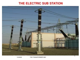
THE ELECTRIC SUB STATION. 1/2/2020. THE TRANSFORMER BAY. 1. THE ELECTRIC SUB STATION. 1/2/2020. M L SHESHADRI. 2. INTRODUCTION

E N D
THE ELECTRIC SUB STATION 1/2/2020 THE TRANSFORMER BAY 1
THE ELECTRIC SUB STATION 1/2/2020 M L SHESHADRI 2 • INTRODUCTION The present electrical power system is a complex interconnection of Generating stations-Transmission systems- Receiving stations- Distribution systems and Load points. In all the above phases of power flow, thetransfer of electrical energy takes place in the electric sub stations.
THE ELECTRIC SUB STATION 1/2/2020 M L SHESHADRI 3 • INTRODUCTION • Basically an electrical sub station consists of a number of incoming circuits and out going circuits connected to common bus bar systems. • Bus bars are conducting bars to which a number of incoming or out going circuits are connected.
THE ELECTRIC SUB STATION 1/2/2020 M L SHESHADRI 4 • INTRODUCTION Each circuit connected to the bus bar will have certain electrical component such as circuit breakers, isolators, earth switches, current transformers and voltage transformers. These components are connected in a definite sequence such that a circuit can be switched off during normal operation by manual command and also automatically during abnormal conditions such as short circuits.
THE ELECTRIC SUB STATION 1/2/2020 M L SHESHADRI 5 • INTRODUCTION A sub station receives electrical power from generating station through incoming transmission lines and delivers electrical power through the out going transmission lines. Sub station is an integral part of a power system and is an important link between the generating stations, transmission systems, distribution systems and load points.
THE ELECTRIC SUB STATION 1/2/2020 M L SHESHADRI 6 • DESIGN CONSIDERATIONS • The sub station is designed with an objective to provide maximum reliability, flexibility, continuity of service and to meet these objectives with the lowest investment costs that satisfy system requirement.
THE ELECTRIC SUB STATION 1/2/2020 • System requirements include the selection of optimum voltage levels depending on the load requirements and the transmission distances involved. Generally, the generating source will be far away from the load centers. The advantage of capitalizing on low site costs, availability of ample cooling water supply, economical fuel supply and less stringent environmental considerations compel construction of generating source far away from load centers, there by, increasing transmission distances. M L SHESHADRI 7 • DESIGN CONSIDERATIONS
THE ELECTRIC SUB STATION 1/2/2020 M L SHESHADRI 8 • DESIGN CONSIDERATIONS • Hence, to transmit power over long distances the transmission voltage is to be increased and in our country 400 kV is becoming common and higher voltages for transmission is being explored. Many factors such as voltage level, load capacity, site space limitations, transmission line right of way requirement and environmental considerations influence the design of sub stations. • The system requirement must be met with minimum costs as the cost of equipment, labor, land and site treatment is increasing every day.
THE ELECTRIC SUB STATION 1/2/2020 M L SHESHADRI 9 • BUS LAYOUT AND SWITCHING ARRANGEMENT • Since the major sub station costs are reflected in the power transformers, circuit breakers and disconnecting switches, the bus layout and switching arrangement selected will determine the number of switches and power circuit breakers required. • A number of factors must be considered in the selection of bus layouts and switching arrangements for a sub station to meet system and station requirements. • A sub station must be reliable, economical, safe, and as simple in design as possible.
THE ELECTRIC SUB STATION 1/2/2020 M L SHESHADRI 10 • SUB STATION LAYOUT AND BUS BAR SCHEMES • The term layout denotes the physical arrangement of various components in the sub station relative to one another. The layout is significant as it influences the operation, maintenance, cost and protection of the sub station. These aspects are considered while designing the sub station layout.
THE ELECTRIC SUB STATION 1/2/2020 M L SHESHADRI 11 • SUB STATION LAYOUT AND BUS BAR SCHEMES With the given number of incoming lines, out going lines, transformers, etc., the sub station can be designed in several alternative ways. • The physical arrangement of the equipment is called the layout of the sub station. The layout is illustrated by means of single line diagrams. • The design of sub station layout need careful consideration of several aspects such as:
THE ELECTRIC SUB STATION 1/2/2020 M L SHESHADRI 12 • SUB STATION LAYOUT AND BUS BAR SCHEMES • Switching requirement for normal operation. • Switching requirement during abnormal conditions like short circuits and overloads. • Degree of flexibility in operations, simplicity. • Freedom from total shutdowns. • Maintenance requirements, space for approaching various equipment for maintenance. • Road/ rail for transporting main and auxiliary equipment.
THE ELECTRIC SUB STATION 1/2/2020 M L SHESHADRI 13 • SUB STATION LAYOUT AND BUS BAR SCHEMES • Safety of personnel. • Protective zones for main and back up protection. • Provision for bye pass facilities and for extensions, space requirements. • Technical requirements such as ratings, clearances, earth system, lightning protection. • Requirement for SCADA and communication. • Compatibility for local and ambient condition.
THE ELECTRIC SUB STATION 1/2/2020 M L SHESHADRI 14 • SUB STATION LAYOUT AND BUS BAR SCHEMES • The choice of bus bar schemes for ac yards depend upon several factors mentioned above. The important bus bar schemes are: • Single bus bar • Double bus bar with one breaker per circuit • Double bus bar with two breaker per circuit • Main and transfer bus • Ring bus or Mesh scheme • Breaker and a half(1 1/2 breaker) arrangement
THE ELECTRIC SUB STATION 1/2/2020 M L SHESHADRI 15 • SUB STATION LAYOUT AND BUS BAR SCHEMES The various schemes are generally compared to emphasize their advantage and limitations. • The basis of comparison is generally the degree of reliability & economic justification. • The degree of reliability is evaluated by determining continuity of service under anticipated operating conditions and possible faults.
THE ELECTRIC SUB STATION 1/2/2020 BUS ISOLATOR M L SHESHADRI BREAKER CURRENT TRANSFORMER POWER TRANSFORMER 16 • VARIOUS BUS BAR SCHEMES • SINGLE BUS BAR SCHEME
THE ELECTRIC SUB STATION 1/2/2020 M L SHESHADRI 17 • SINGLE BUS BAR SCHEME • Advantage –Lowest cost • Disadvantage: Maintenance without interruption of supply is not possible. Sub station can not be extended without completely de-energizing the sub station Can be used only where loads can be interrupted or have other supply arrangements. Least flexibility.
THE ELECTRIC SUB STATION 1/2/2020 BUSSECTION-1 BUS SECTION-2 SECTIONALISER ISOLATOR M L SHESHADRI BREAKER CURRENT TRANSFORMER POWER TRANSFORMER 18 • VARIOUS BUS BAR SCHEMES • SINGLE BUS BAR SCHEME WITH BUS SECTIONALISER
THE ELECTRIC SUB STATION 1/2/2020 M L SHESHADRI 19 • SINGLE BUS BAR SCHEME WITH BUS SECTIONALISER Sectionalizing the single bus improves slightly the reliability if the incoming and out going circuits are distributed evenly on both the sections. • Where double feed is provided for any single load it is preferable to have one circuit from each section. • In this arrangement each section behaves as a separate bus bar and any outage can be confined to one section of the bus bar. • Only the faulty section will be tripped by bus differential protection.
THE ELECTRIC SUB STATION 1/2/2020 BUS-1 BUS-2 BUS COUPLER BREAKER M L SHESHADRI BREAKER POWER TRANSFORMER 20 • DOUBLE BUS BAR WITH ONE BREAKER PER CIRCUIT
THE ELECTRIC SUB STATION 1/2/2020 M L SHESHADRI 21 • DOUBLE BUS BAR WITH ONE BREAKER PER CIRCUIT • This arrangement has the following advantages: • Each load may be fed from either bus. • Operational flexibility may be increased by grouping the incoming and out going feeders in separate groups. • Either bus bar can be taken out for maintenance. • Bus coupler helps in ‘on load change over ‘from one bus to the other. • Adopted where load and continuity justify additional cost. • A major disadvantage is that the breaker can not be taken out for maintenance without interrupting supply to the concerned circuit.
THE ELECTRIC SUB STATION 1/2/2020 M L SHESHADRI 22 • DOUBLE BUS BAR WITH ONE BREAKER PER CIRCUIT • Bus protection scheme may cause loss of sub station when it operates if all circuits are connected to that bus. • High exposure to bus faults. • Line breaker failure takes all circuits connected to that bus out of service. • Bus tie breaker failure takes the entire sub station out of service.
DOUBLE MAIN BUS & CB BYPASS ISOLATOR SYSTEM T/F-1 T/F-2 BAY1 BAY2 BAY6 BAY4 BAY7 BUS-1 BUS COUPLER BUS-2 BAY5 BAY3 FOR ANY CB PROBLEM OR FOR PREVENTIVE MAINTANENCE, SUCH FEEDER CAN BE SHIFTED TO ANOTHER BUS AND THE BYPASS ISOLATOR IS CLOSED, THEN PROTECTION IS TRANSFERRED TO BUS COUPLER AND THE FAULTY CB CAN BE ISOLATED. FEEDER2 FEEDER3 FEEDER4 FEEDER1
THE ELECTRIC SUB STATION 1/2/2020 MAIN BUS TIE BREAKER BREAKER TRANSFER BUS M L SHESHADRI LINE LINE 24 • MAIN AND TRANSFER BUS
THE ELECTRIC SUB STATION 1/2/2020 M L SHESHADRI 25 • MAIN AND TRANSFER BUS • This is an alternative to double bus single breaker arrangement which provided for change over to either bus for carrying out maintenance on other bus. But it provided no facility for breaker maintenance without interrupting power supply to the concerned circuit. • The main and transfer bus works the other way round. • This arrangement provides facility for carrying out breaker maintenance but does not permit bus maintenance.
THE ELECTRIC SUB STATION 1/2/2020 M L SHESHADRI 26 • MAIN AND TRANSFER BUS • Any breaker can be taken out of service for maintenance. • Wherever maintenance is required on any breaker, the circuit is changed over to the transfer bus and controlled through the bus coupler breaker. • Potential devices may be used on the main bus for relaying. • The cost is increased due to use of an extra isolator for each circuit and providing interlock for bus coupler and circuit isolators. • Relaying sensitivity decreases as the same bus coupler is used to energize the concerned circuit for all the circuit breakers whenever they are taken out for maintenance. • Failure of bus or any circuit breaker results in shut down of entire sub station.
DOUBLE MAIN BUS & TRANSFER BUS SYSTEM T/F-1 T/F-2 BUS-1 BUS COUPLER BUS-2 TRANSFER BUS COUPLER BAY3 BAY5 BAY4 BAY6 BAY2 BAY7 TRANSFER BUS BAY8 BAY1 FEEDER1 FEEDER3 FEEDER2 FEEDER4
BUS BAR ARRANGEMENTS • Double Bus Bar Arrangement with Transfer Bus. This arrangement provides more additional flexibility, continuity of Power Supply, permits periodic maintenance without total shut down as the two main buses can be operated independently with the same redundancy.
THE ELECTRIC SUB STATION 1/2/2020 BUS-1 BREAKER M L SHESHADRI BUS-2 29 LINE • DOUBLE BUS BAR WITH TWO BREAKER PER CIRCUIT LINE
THE ELECTRIC SUB STATION 1/2/2020 M L SHESHADRI 30 • DOUBLE BUS BAR WITH TWO BREAKER PER CIRCUIT • Each circuit has two dedicated breakers. • Has flexibility in permitting feeder circuits to be connected to either bus. • Any breaker can be taken out of service for maintenance. • High reliability. • Most expensive. Used only in large generating stations where security of connection is paramount.
THE ELECTRIC SUB STATION 1/2/2020 ISOLATOR BREAKER LINE M L SHESHADRI POWER TRANSFORMER LINE 31 RING BUS OR MESH SCHEME
THE ELECTRIC SUB STATION 1/2/2020 M L SHESHADRI 32 • RING BUS OR MESH SCHEME • In this scheme the breakers are arranged in a ring with circuits connected between breakers. • There are the same number of circuits as there are breakers. • During normal operation, all breakers are closed. For a circuit fault, two breakers are tripped, and in the event one of the breaker fails to operate to clear the fault, an additional circuit will be tripped by operation of breaker- failure back up relays. • During breaker maintenance, the ring is broken, but all lines remain in service.
THE ELECTRIC SUB STATION 1/2/2020 M L SHESHADRI 33 • RING BUS OR MESH SCHEME • The circuits connected to the ring are arranged so that sources are alternated with loads. • For an extended circuit outage, the line isolator may be opened and the ring can be closed. • No changes to protective relays are required for any of the various operating conditions or during maintenance. • The ring bus scheme is economical in cost, has good reliability, is safe for operation, is flexible, and is normally considered suitable for important sub stations up to a limit of five circuits. • It is common practice to build major sub stations initially as a ring bus; for more than five outgoing circuits, the ring bus is usually developed to the breaker-and-a-half scheme.
THE ELECTRIC SUB STATION • One and a Half Breaker Arrangement. This arrangement provides three circuit breakers for every two circuits. It gives high security against loss of supply but higher cost is involved. Hence this is provided for important 400/220 KV Sub Stations.
THE ELECTRIC SUB STATION 1/2/2020 BUS-1 ISOLATOR BREAKER LINE M L SHESHADRI TIE BREAKER 35 BREAKER -AND -A -HALF SCHEME BUS-2
I-CONFIGUARATION FEEDER1 FEEDER3 FEEDER5 FEEDER9 FEEDER7 FEEDER11 BUS-1 DIA4 DIA5 DIA2 DIA3 DIA6 DIA1 BAY10 BAY13 BAY16 BAY4 BAY7 BAY1 BAY11 BAY14 BAY17 BAY8 BAY2 BAY5 BAY12 BAY18 BAY9 BAY15 BAY3 BAY6 BUS-2 FEEDER2 FEEDER4 FEEDER6 FEEDER10 FEEDER8 FEEDER12
D-CONFIGUARATION FEEDER5 FEEDER6 FEEDER9 FEEDER1 FEEDER2 FEEDER10 BAY2 BAY8 BAY14 DIA5 DIA3 DIA1 BAY13 BAY15 BAY3 BAY9 BAY1 BAY7 BUS-1 BUS-2 BAY18 BAY6 DIA6 BAY4 DIA4 BAY10 BAY12 DIA2 BAY16 BAY5 BAY11 BAY17 FEEDER3 FEEDER4 FEEDER7 FEEDER8 FEEDER11 FEEDER12
THE ELECTRIC SUB STATION 1/2/2020 M L SHESHADRI 38 • BREAKER -AND -A -HALF SCHEME • The breaker and a half scheme, some times called the three switch scheme, has three breakers in series between the main buses. • Two circuits are connected between the three breakers, hence the term breaker and a half. • This pattern is repeated along the main buses so that one and a half breakers are used for each circuit.
THE ELECTRIC SUB STATION 1/2/2020 M L SHESHADRI 39 • BREAKER -AND -A -HALF SCHEME • Under normal operating conditions all breakers are closed and both buses are energized. • A circuit is tripped by opening the two associated circuit breakers. • Tie breaker failure will trip one additional circuit, but no additional circuit is lost if a line trip involves failure of a bus breaker. • Either bus may be taken out of service at any time with no loss of service. • With sources connected opposite loads, it is possible to operate with both buses out of service. • Breaker maintenance can be done with no loss of service, no relay changes, and simple operation of the breaker isolators.
THE ELECTRIC SUB STATION 1/2/2020 M L SHESHADRI 40 • BREAKER -AND -A -HALF SCHEME • The breaker-and-a-half arrangement is more expensive than other schemes, except the double-breaker-double-bus scheme. • However, the breaker-and-a-half scheme is superior in flexibility, reliability, and safety. • Protective relaying and automatic re-closing schemes are more complex than for other schemes and hence costly.
THANK YOU 1/2/2020 M L SHESHADRI 41 ANY QUESTIONS ?