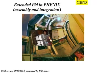
HF assembly, commissioning and integration
170 likes | 333 Vues
HF assembly, commissioning and integration. Ianos schmidt The University of Iowa. HF, TOTEM, and CASTOR. HF Outer shielding. HF “metallic structures”. TOTEM platform. CASTOR. TOTEM T2. HF racks. CASTOR racks. HF table. HF readout boxes. Castor table. HF shielding plug.

HF assembly, commissioning and integration
E N D
Presentation Transcript
HF assembly, commissioning and integration Ianos schmidt The University of Iowa HCAL Fall meeting Oct 11 to 13, 2004
HF, TOTEM, and CASTOR HF Outer shielding HF “metallic structures” TOTEM platform CASTOR TOTEM T2 HF racks CASTOR racks HF table HF readout boxes Castor table HF shielding plug HCAL Fall meeting Oct 11 to 13, 2004
HF Cables and services • Nearly all of the HF specific cables and services have been defined. • Lengths of cables from the cable chain to the HF racks are relatively short so no patch panels near the cable chains have been foreseen for HF specific cables. • Cable definitions and cross-sections have been provided to the integration group for specification of the flexible cable chains. * Small flexible cable chains are needed between the HF table and the metallic structures to allow for opening of the HF. Cables and services to cable chain HCAL Fall meeting Oct 11 to 13, 2004
Cables and services within the HF shielding Cables and services from the readout boxes and HF wedges are routed along the inner surface of the outer shielding. Upper and lower ports are provided in the shielding for cables that go to the upper and lower electronics racks respectively. A central port is also provided to allow passage of the source tube conduits to the source drivers located outside the shielding. *It may be possible to produce cable harnesses that can be installed as a complete units, allowing production to go in parallel with other activities. HF outer shielding Cables to Upper rack Source Tube conduits Cables to Lower rack Readout boxes HCAL Fall meeting Oct 11 to 13, 2004
Cables and services within the HF shielding cont. Cables and services will be supported within the shielding by braces spaced at ~10 degree intervals. Cable cross section HF readout box HF outer shielding Cable braces Cable brace HCAL Fall meeting Oct 11 to 13, 2004
Front end cable storage The length of the front end cables is fixed at 5 meters to minimize the effects of reflections in the cables. Because of this provisions must be made for storage of the excess cable length outside of the shielding. 8 Cables/readout box x18 boxes on each side of each HF =144 cables on each side of each HF Must store approximately 500 meters of cable on each side of HF. HCAL Fall meeting Oct 11 to 13, 2004
Source tubes and drivers Source driver (2 positions) Each wedge contains 31 source tubes. The plastic tubing is contained within flexible metal conduits. Source tube Conduit port Source drivers are located under the floor of the upper level metallic structures. A rotating table is foreseen to support the drivers allowing them to be moved into a position where they can be accessed through a hatch in the floor. Source conduits HCAL Fall meeting Oct 11 to 13, 2004
From S.Bally’s database HF cable chain specification Telephone and computer network cables need to be added to the cable chain specification HCAL Fall meeting Oct 11 to 13, 2004
HF cable status Many of these items can potentially be shared between sub-detectors HCAL Fall meeting Oct 11 to 13, 2004
HF Rack cooling requirements 34U rack Turbine 300W DCS RS/RS hub ~10W FE electronics crate 150W * FE electronics crate 150W * FE electronics crate 150W * TOTAL per rack 760W X4 racks/HF =3040W X2 HF’s =6080W for all HF Total heat load is safely below the approximate 1kW limit imposed by the use of a single heat exchanger .(Heat exchanger is to be moved to top of rack) *Prototype FE crate measured to be ~85W. (Safety factor of about 50%) AC to DC converter (water cooled) May be placed inside rack HCAL Fall meeting Oct 11 to 13, 2004
HF gas requirements Date: Wed, 10 Mar 2004 11:59:10 +0100 (CET) From: Dragoslav-Laza Lazic <dlazic@mail.cern.ch> To: Christoph Schaefer <Christoph.Schaefer@cern.ch> 3) HF has photomultiplier based readout. HV discharge danger and helium leaks are points of concern. In addition, the HF absorber is made of iron and requires relatively dry atmosphere (less than 20% humidity at room temperature) in order to minimize deterioration due to oxidation. The readout boxes of HF have been made so that they enable flow of nitrogen from the photomultiplier tubes into the absorber. Tests have shown that a satisfactory levels of oxygen content and relative humidity can be achieved with flows of ~5 l/hr*HF wedge. Given that there are 36 HF wedges it amounts to the total requirement of 180 l/hr. N.B. This is considered to be a necessary condition, it may be possible that a safety factor of two for HF nitrogen inerting has to be implemented in case the humidity control of the UXC proves to be inadequate, especially in the early days while the concrete is not fully dried. =360 l/hr HF Gas distribution system needs to be designed! HCAL Fall meeting Oct 11 to 13, 2004
To do (draft) • Installation of metallic structures • Delivery of HF racks • Installation of electrical infrastructure (50Hz and 500Hz) • Installation of cable trays and cabling infrastructure (ie. Patch panels…) • Installation of cooling and gas services • Installation of table actuator systems • Installation of HF specific cables and services • Installation of TOTEM specific cables and services • Installation of CASTOR specific cables and services • Cabling of UXC cable chains • Final cabling of each sub-detector in UXC HCAL Fall meeting Oct 11 to 13, 2004
HF cabling and integration workshop Sept.`04 What was discussed: • 1. TOTEM and CASTOR. General parameters are fixed so more detailed • design work can proceed. It is not clear if there is sufficient • support for CASTOR. • 2.) There was extensive discussion about the tender for the HF cable • chain. There have been two acceptable bids, but each does not quite meet • all of the requirements. Plan to invite vendors to CERN to clarify details. • 2b.) Many ideas were raised about locations of patch panels (CASTOR,TOTEM) • and fixation of the cable chains to the HF platforms. Design of the cable • chain attachment and the CASTOR patch panels is of high priority to avoid • conflict with the cable chain installation schedule. • No work has happened on this since the workshop! • 3.) HF racks had not been ordered. Apparently they were waiting for us • to give the final word. the green light to order the racks was given, and racks are • expected this month. The proposed rack layout is acceptable, except that the • heat exchanger should be moved from the bottom to the top of the rack. HCAL Fall meeting Oct 11 to 13, 2004
3b.) It is possible that the HCAL AC to DC converters will be placed within • the HF racks. The cooling requirements (water) for these supplies need to • be specified. • This info has been provided by Serguei Lusin. • 4.) Orders for the HF metallic structures have just gone out. Date of • arrival at CERN is not yet known. It is believed to be sometime before • the end of the year. • Now expect arrival in December. • 5.) The design efforts for cable trays is a shared effort between the • sub-detector groups and Jean Claude (Alain’s group). Generally there was a preference to • wait until the arrival of the metallic structures before starting this • effort. For the HF HV cable I will make a proposal for routing and • provide a sub-set of "intermediate" lengths so that cable production can • start. With this plan we hope have some HV cables in hand after the • metallic structures are installed so that lengths can be verified. HCAL Fall meeting Oct 11 to 13, 2004
6.) The need to store ~500 meters of HF front end cable outside of the HF shielding was raised. The cable storage will again be assessed after installation of the metallic structures. 7.) Poly intended to cover the exterior of the HF outer shielding will come at a later date only if it is determined to be necessary. The cable trays etc. should be designed with this possibility in mind. 8.) The Gas distribution system on HF is the responsibility of HF. Gas will be provided to the HF but we must provide the design for flow regulators, manifolds, etc. (at the moment there is no person in HCAL to do this work). 9.) The HF garages in the UXC will be equipped with 50Hz power and lights. All other HF specific services will be part of the HF cable chain. We need to add telephone and network cables to our HF cable requirements. 10.) A list of "undefined" services was discussed and responsible groups/people we identified to make sure all bases were covered. HCAL Fall meeting Oct 11 to 13, 2004
HF specific integration issue summary • Cable trays and cable routing on the HF metallic structures need to be defined so that cable lengths can be determined. This is holding up cable orders and production. • Definition of cable storage space and support. • Checking of source driver support, access, and tubing conduit fixation • Placement of AC/DC converters. • Final design of the cable trays and chains that go from the main cable chain to the HF racks. * • Design of the systems related each of the undefined services (CERN responsibility). * The lengths of the HF trigger readout fibers are critical, so a check must be made to see if the trigger cables do not need an alternative path to keep within the latency budget. This may require designing an alternative path for these cables within the interface between the castor and HF tables. HCAL Fall meeting Oct 11 to 13, 2004
HCAL Group specific activities (rough draft) • *Very rough estimates of time required(-0,+50%) • *Cable production and installation prep. TBD • *light guide production In progress, Likely completed by end of year. • * installation of gas distribution system (HCAL?) TBD • Installation of light guides and readout boxes ~2 FTE weeks/HF(split b/t two people) • Cabling of inner shielding ~4 FTE weeks/HF • Populating racks and cabling electronics ~2 FTE weeks/HF • Installation of source drivers and connection of tubes ~2 FTE weeks/HF • Installation of remaining HF specific items • (rad monitors …) ~1 FTE week/HF • Calibration and testing ~3 FTE weeks/HF • Electronics burn in (can be done in UXC) HCAL Fall meeting Oct 11 to 13, 2004