Download
1 / 78
970 likes | 1.6k Vues
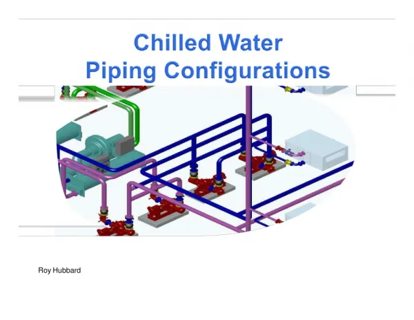
Roy Hubbard. A g e nda. Understanding the three basic piping systems Design and Off-design operation Advantages and Disadvantages Low DeltaT Syndrome – causes, effects, and solutions Design & Control Considerations (VPF) Chillers CHW Pumps Bypass Valve. 4.

E N D
Agenda • Understanding the three basic pipingsystems • Design and Off-designoperation • Advantages andDisadvantages • Low DeltaT Syndrome – causes, effects, andsolutions • Design & Control Considerations(VPF) • Chillers • CHWPumps • BypassValve 4
LoadEquation Load = Flow XDeltaT SecondaryPumps 4
Constant Primary Flow(CPF) SecondaryPumps 4
Load = Flow XDeltaT Constant Primary Flow(CPF) DedicatedPumping SecondaryPumps 4
Constant Primary Flow atDesign 56ºF (13.3ºC) SecondaryPumps 56ºF (13.3ºC) (189 l/s) @ 6.7ºC) 56ºF (13.3ºC) (1760kW) (63l/s) 56ºF (13.3ºC) (189 l/s) @ 13.3ºC) 4
Constant Primary Flow at 75%Load 75% 53ºF (11.7ºC) SecondaryPumps 53ºF (11.7ºC) (189 l/s) @ 6.7ºC) 53ºF (11.7ºC) (1760kW) (63l/s) 56ºF (13.3ºC) 53ºF 53ºF (11.7ºC) (189 l/s) @ 11.7ºC) 8
Constant Primary Flow at 50%Load 50% 50ºF (10ºC) SecondaryPumps 50ºF (10ºC) (189 l/s) @ 6.7ºC) 50ºF (10ºC) (1760kW) (63l/s) 56ºF (13.3ºC) 50ºF (189 l/s) @ 10ºC) 50ºF (10ºC) 9
Constant Primary Flow at 25%Load 25% 47ºF (8.3ºC) SecondaryPumps 47ºF (8.3ºC) (189 l/s) @ 6.7ºC) 47 ºF (8.3ºC) (1760kW) (63l/s) 56ºF (13.3ºC) 47ºF (189 l/s) @ 8.3ºC) 47ºF (8.3ºC)
Constant FlowPrimary • Advantages • Lowest installedcost • Less plant space thanP/S • Easy to Control &Operate • Easy toCommission • Disadvantages • Highest Plant Energy Cost (must run all, even at lowloads)
Primary (Constant) / Secondary(Variable) SLoad = Flow XDeltaT SecondaryPumps PLoad = Flow XDeltaT
Primary (Constant) / Secondary(Variable) Headered Pumping SecondaryPumps
Primary (Constant) / Secondary(Variable) DedicatedPumping SecondaryPumps
Primary (Constant) / Secondary(Variable) Rule ofFlow Primary flow must always be equal to or greater thanSecondaryflow. SecondaryPumps
Primary/Secondary atDesign 100% Load = 100% SecFlow 56ºF (13.3ºC) SecondaryPum ps ºF C 3000 GPM @44 189 l/s @ 6.7º 100 ft (303 kPa)Head 56ºF (13.3ºC) 56ºF (13.3ºC) 44.0 °F (6.7°C) (1760kW) 0 GPM @ 44ºF 0 l/s @ 6.7ºC (63l/s) 3000 GPM @ 56ºF 56ºF (13.3ºC) (189 l/s) @ 13.3ºC) (189 l/s) @ 13.3ºC) 50 ft (152 kPa)Head
Primary/Secondary at 75%Load 75% Load = 75% SecFlow 75% 53ºF (11.7ºC) SecondaryPumps 2250 GPM @ 44ºF 142 l/s @ 6.7ºC 53ºF (11.7ºC) 53ºF (11.7ºC) 44.0 °F (6.7°C) (1760kW) 750 GPM @ 44ºF 47 l/s @ 6.7ºC (63l/s) 2250 GPM @ 56ºF 3000 GPM @ 53ºF (189 l/s) @ 11.7ºC) 56ºF (13.3ºC) (142 l/s) @ 13.3ºC)
Primary/Secondary at 50%Load 50% Load = 50% SecFlow 50% Secondary Pumps 1500 GPM @ 44ºF 95 l/s @ 6.7ºC 53ºF (11.7ºC) 53ºF (11.7ºC) 44.0 °F (6.7°C) (1760kW) 500 GPM @ 44ºF 32 l/s @ 6.7ºC (63l/s) 1500 GPM @ 56ºF 2000 GPM @ 53ºF (126 l/s) @ 11.7ºC) 56ºF (13.3ºC) (95 l/s) @ 13.3ºC)
Primary/Secondary at 25%Load 25% Load = 25% SecFlow 25% SecondaryPumps 750 GPM @ 44ºF 47 l/s @ 6.7ºC 53ºF (11.7ºC) 44.0 °F (6.7°C) (1760kW) 250 GPM @ 44ºF 16 l/s @ 6.7ºC (63l/s) 750 GPM @ 56ºF 1000 GPM @ 53ºF (63 l/s) @ 11.7ºC) 56ºF (13.3ºC) (47l/s) @ 13.3ºC)
What Controls the Flow of the SecondaryLoop? But what controls theVSD’s?
Valve Controls Leaving Air Temperature (LAT) Set Point = 55º (12.8º)LAT T
Valve Controls Leaving Air Temperature (LAT) Set Point = 55º (12.8º)LAT T
Valve Controls Leaving Air Temperature (LAT) Set Point = 55º (12.8º)LAT T
As Valve Opens, Pressure in loop lowers As Valve Closes, Pressure in looprises
Pressure Differential Sensor Controls Secondary PumpSpeed • Differential Pressure sensor on lastcoil • controls speed • to Set Point (coil WPD+Valve PD+PipingPD+Safety) • located at end of Index Circuit for bestefficiency SetPoint P=25 ft (76kPa) P
Primary (Constant) / Secondary(Variable) • Advantages • Easy toControl • Easy toCommission • Loopseparation • Easiertrouble-shooting • Separating isolated loads/buildings for lower total pumpenergy • Lower Plant Energy (can sequence chillers and ancillaryequipment) • Versatile – multi-circuitcapability • Disadvantages • Medium Pump EnergyCost • Highest Installed Cost (Sec Pumps, Piping,etc.) • Potential for higher plant energy loss because of Low Delta Tsyndrome
Load = Flow XDeltaT Variable PrimaryFlow Variable Primary Flow at 100% System Load Two-way valves control capacity By varying flow of water incoils PrimaryPumps Chillers Closed 30
Primary/SecondarySystem ThreeDifferences? Variable PrimarySystem PrimaryChillers Pumps 30
Variable Primary Flow atDesign Variable PrimaryFlow at 100% System Load Two-way valves control capacity By varying flow of water incoils 100% Load = 100%Flow 56ºF (13.3ºC) 3000 GPM @ 44ºF 189 l/s @ 6.7ºC 56ºF (13.3ºC) 56ºF (13.3ºC) 44.0°F (6.7°C) 0 GPM @ 44ºF 500 Ton (1760kW) Primary Pumps 1000 GPMeach (63l/s) 0 l/s @ 6.7ºC Chillers Closed 3000 GPM @ 56ºF (189 l/s) @ 13.3ºC) 3000 GPM @ 56ºF (189 l/s) @ 13.3ºC) 56ºF (13.3ºC) 30
Variable Primary Flow at 75%Load Variable PrimaryFlow at 75% SystemLoad Two-way valves control capacity By varying flow of water incoils 75% Load = 75%Flow 56ºF (13.3ºC) 2250 GPM @ 44ºF 142 l/s @ 6.7ºC 56ºF (13.3ºC) 56ºF (13.3ºC) 44.0°F (6.7°C) 0 GPM @ 44ºF PrimaryPumps 750 GPMeach (47l/s) 0 l/s @ 6.7ºC Closed 2250 GPM @ 56ºF 2250 GPM @ 56ºF 56ºF (142 l/s) @ 13.3ºC) (142 l/s) @ 13.3ºC) (13.3ºC) 33
Variable Primary Flow at 50%Load Variable PrimaryFlow at 50% SystemLoad Two-way valves control capacity By varying flow of water incoils 50% Load = 50%Flow 1500 GPM @ 44ºF 95 l/s @ 6.7ºC 56ºF (13.3ºC) 56ºF (13.3ºC) 44.0°F (6.7°C) 0 GPM @ 44ºF PrimaryPumps 750 GPMeach (47l/s) 0 l/s @ 6.7ºC Closed 1500 GPM @ 56ºF 1500 GPM @ 56ºF 56ºF (95 l/s) @ 13.3ºC) (95 l/s) @ 13.3ºC) (13.3ºC) 34
Variable Primary Flow at 25%Load Variable PrimaryFlow at 25% SystemLoad Two-way valves control capacity By varying flow of water incoils 25% Load = 25%Flow 750 GPM @ 44ºF 47 l/s @ 6.7ºC 56ºF (13.3ºC) 44.0°F (6.7°C) 0 GPM @ 44ºF PrimaryPumps 750GPM (47l/s) 0 l/s @ 6.7ºC Closed 750 GPM @ 56ºF (47 l/s) @ 13.3ºC) 750 GPM @ 56ºF (47 l/s) @ 13.3ºC) 56ºF (13.3ºC) 35
Variable Primary Flow in Bypass Mode System flow below chiller min flow (250gpm) Variable PrimaryFlow at 25% SystemLoad Two-way valves control capacity By varying flow of water incoils 100 GPM @ 44ºF 6.3 l/s @ 6.7ºC 48.8 ºF (9.3ºC) 44.0°F (6.7°C) 150 GPM @ 44ºF PrimaryPumps 250GPM (15.8l/s) 9.5 l/s @ 6.7ºC Open 250 GPM @ 48.8ºF (15.8 l/s) @ 9.3ºC) 100 GPM @ 56ºF (6.3 l/s) @ 13.3ºC) 56ºF (13.3ºC) 37
Varying Flow Through Chillers -Issues • Issue During NormalOperation • Chiller Type (centrifugal fast, absorbersslow) • Chiller Load (min load - no variance, full load - maxvariance) • System Water Volume (more water, more thermal capacitance, faster varianceallowed) • Active Loads (near or far fromplant) • Typical VSD pump ramp rate setting of 10%/minute (accel/decel rates set to 600seconds) 37
Varying Flow Through Chillers -Issues • Issue During NormalOperation • Chiller Type (centrifugal fast, absorbersslow) • Chiller Load (min load - no variance, full load - maxvariance) • System Water Volume (more water, more thermal capacitance, faster varianceallowed) • Active Loads (near or far fromplant) • Typical VSD pump ramp rate setting of 10%/minute (accel/decel rates set to 600seconds) 37
Varying Flow Through Chillers -Issues • Issue During NormalOperation • Chiller Type (centrifugal fast, absorbersslow) • Chiller Load (min load - no variance, full load - maxvariance) • System Water Volume (more water, more thermal capacitance, faster varianceallowed) • Active Loads (near or far fromplant) • Typical VSD pump ramp rate setting of 10%/minute (accel/decel rates set to 600seconds) • Issue AddingChillers • Modulating isolation valves onchillers 37
Variable Primary System – Staging on chillers & changes in flowrate Current Situation – 1 chillerrunning Variable PrimaryFlow at 100% System Load Two-way valves control capacity By varying flow of water incoils 1000 GPM @ 44ºF 63 l/s @ 6.7ºC 44.0 °F (6.7°C) PrimaryPumps 500 GPMeach (32l/s) Closed 1000 GPM @ 56ºF (63 l/s) @ 13.3ºC) 56ºF (13.3ºC) 40
Variable Primary System – Staging on chillers & changes in flowrate Current Situation –building load increases, valve opens, second chillerstarts Variable PrimaryFlow at 100% System Load Two-way valves control capacity By varying flow of water incoils If valve opens tooquick: Chiller1 shuts down on low ch water tempcutout illed Bestpractice! Open valve over 1.5 to 2 minutesto allow for systemstabilization 1100 GPM @ 45ºF 69 l/s @ 7.2ºC 45.0 °F (7.2°C) PrimaryPumps 550 GPMeach (35l/s) Closed 1100 GPM @ 57ºF (69 l/s) @ 13.9ºC) 57ºF (13.9ºC) 48
Variable Primary Flow (VPF) SystemArrangement • Advantages • Lower Installed Cost (approx. 5% comparedP/S) • No secondary Pumps or piping, valves, electrical, installation,etc. • Offset somewhat by added 2W Bypass Valve and more complexcontrols • Less Plant SpaceNeeded • Best Chilled Water Pump Energy Consumption (most optimeadyconfiguration) • VSD energysavings • Lower Pump DesignHead 48
Primary/Secondary 56ºF (13.3ºC) SecondaryPumps 3000 GPM @ 44ºF 189 l/s @ 6.7ºC 100 ft (303 kPa)Head 56ºF (13.3ºC) 56ºF (13.3ºC) 44.0 °F (6.7°C) (1760kW) 0 GPM @ 44ºF 0 l/s @ 6.7ºC (63l/s) 3000 GPM @ 56ºF 56ºF (13.3ºC) (189 l/s) @ 13.3ºC) (189 l/s) @ 13.3ºC) 50 ft (152 kPa)Head 48
Variable PrimaryFlow Variable PrimaryFlow at 100% System Load Two-way valves control capacity By varying flow of water incoils 56ºF (13.3ºC) 3000 GPM @ 44ºF 189 l/s @ 6.7ºC 56ºF (13.3ºC) 56ºF (13.3ºC) 44.0°F (6.7°C) 0 GPM @ 44ºF 500 Ton (1760kW) Primary Pumps 1000 GPMeach (63l/s) 0 l/s @ 6.7ºC Chillers Closed 3000 GPM @ 56ºF (189 l/s) @ 13.3ºC) 3000 GPM @ 56ºF (189 l/s) @ 13.3ºC) 56ºF (13.3ºC) 140 ft (424 kPa)Head 48
PumpEnergy BHP= GPM X Head 3960 XPumpEff 48
Variable Primary Flow (VPF) SystemArrangement • Advantages • Lower Installed Cost (approx. 5% comparedP/S) • No secondary Pumps or piping, valves, electrical, installation,etc. • Offset somewhat by added 2W Bypass Valve and more complexcontrols • Less Plant SpaceNeeded • Best Chilled Water Pump Energy Consumption (most optimeadyconfiguration) • VSD energysavings • Lower Pump DesignHead • Higher PumpEfficiency 48
Pump Curves - PumpEfficiency With VPF you will need larger pumps compared to P/S, but they will be operating at a more efficient point, yielding energysavings 48
PumpEnergy BHP= GPM X Head 3960 XPumpEff 48
Variable Primary Flow (VPF) SystemArrangement • Advantages • Medium Installed Cost (approx. 5% comparedP/S) • No secondary Pumps or piping, valves, electrical, installation,etc. • Offset somewhat by added 2W Bypass Valve and more complexcontrols • Less Plant Space Needed (vsP/S) • Best Chilled Water Pump Energy Consumption (most optimeadyconfiguration) • VSD energysavings • Lower Pump DesignHead • Higher PumpEfficiency • Lower potential impact from Low Delta T (can over pump chillers ifneeded)