Download
1 / 11
110 likes | 123 Vues
This study discusses the design and studies of RIA fragment separators, including the High-Resolution Separator and Preseparator, for optimal beam production.

E N D
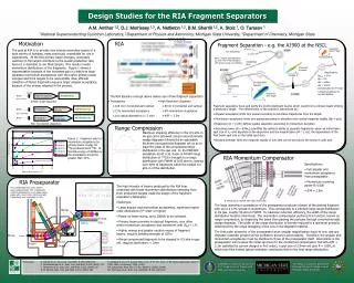
Design Studies for RIA Fragment Separators A.M. Amthor National Superconducting Cyclotron Laboratory, Michigan State University Department of Physics and Astronomy, Michigan State University APS-DNP Fall2004
RIA Concept High-Resolution Separator Large-Acceptance Separator APS-DNP Fall2004
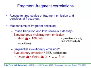
Motivation: ISOL and Gas Stopping Optimum production method for low-energy beams Standard ISOL technique Two-step fission In-flight fission + gas cell Fragmentation + gas cell ISOL Committee Task Force Report (1999) APS-DNP Fall2004
Motivation: Beam Energy and Momentum Acceptance Fragmentation 110Zr ISOL In-flight fission 138Sn Δp/p = 10% 100 114Zr Relative Mass Separated Yields 78Ni 159Nd 10 80Zr 211Fr 11Li 132Sn,96Kr 1 0 100 200 300 400 500 600 700 800 900 1000 1100 1200 E/A ( MeV/u ) Yield (pps/pμA) Momentum Acceptance (%) Above: Fragment beam of 78Ni produced from 86Kr. At the RIA energy of 400MeV/u the acceptance should be greater than 10%. Left: Production of various fragments for fixed current and acceptance. Acceptance determines energy of turnover point (here 10% dp/p) J. Nolen ANL APS-DNP Fall2004
Fragment Separators Fragments after FP Fragments at wedge Fragments after target Z N Z Z N N Note: Isotope yield diagrams are from 86Kr78Ni simulation with primary beam of 140MeV/u Specifications Bρmax = 6Tm Δp/p = 5% Δθ = ±40mr Δφ = ±50mr Compensated to 3rd order Largest acceptance of current facilities APS-DNP Fall2004
Thick Wedges andTwo-stage Fragment Separation CAARI 2004 talk by A. Stolz Al 190 mg/cm2 Al 450 mg/cm2 Al 300 mg/cm2 APS-DNP Fall2004
RIA Separators Target High-Resolution Separator Beam Preseparator High-Energy Area (up to 400 kW) Momentum Compensator Beam Gas-Stopping Cell Preseparator The RIA concept makes use of two fragment separators. • High-Resolution Separator • Maximized quality and purity • Two-stage fragment separation • 80 mr in horizontal and vertical angular acceptance • 6% momentum acceptance • d/M = 2.5m • Preseparator • Maximized production rate • 100 mr in horizontal and vertical • 12% momentum acceptance • low optical aberrations (< 2 mm) APS-DNP Fall2004
Preseparator Dipole Quad Quad Wedge Beam (400kW) Target Beam Dump (160 to 320 kW) Dipole Wedge Quad Quad The compensated third order system passes approximately 73% of fragments uniformly distributed in a 6-D phase space ellipse with a and b from ±50mr and with δ distributed over a full width of 12%. Wedge Isotope Slits Beam • Significant higher order aberrations (>3rd order) • Up to 200kW power on beam dump • Primary beam often within momentum acceptance and sometimes with |δBρ|< 1% • Higher energy and greater neutron excess of fragment beams increases magnetic rigidity (10Tm) • Range compressed fragments to be stopped in 0.5 atm-m gas cell, requires aberrations < 2mm Beam Dump Target Additional wedge at beam dump? Additional stage of separation for gas cell separator? APS-DNP Fall2004
Momentum Compensator 350 MeV/u 130Cd range width Diagram: H. Weick et al., NIM B 164-165 (2000) 168 Range FWHM (atm-m) Resolving Power 130Cd • Specifications: • Full angular and momentum acceptance from preseparator • Momentum resolving power R>1000 • d/M = 2.5m FWHM = 32 atm-m 4He Ion Guide, Cooler and Buncher Gas Cell & Nozzle Monoenergetic Degrader Dispersive Elements FWHM = 0.93 atm-m 4He Insert graph of dependence of gas stopping efficiency on system resolving power from 500 to 2000 (or d/m .5 to 2) Calculate by changing Xo instead of system. Above: Range compression of 350 Mev/u 130Cd produced from 500 MeV/u 136Xe (MOCADI simulation) APS-DNP Fall2004
Simulation Methods& Needed Improvements Fragment production in thick wedges (x|θδ) aberration – angled wedges Dispersive focal plane A. Stolz, CAARI 2004 Profile wedge degrader APS-DNP Fall2004
Acknowledgements Collaborators: B.M. Sherrill 1,2 D.J. Morrissey 1,3 A. Nettleton 1,2 A. Stolz 1 O. Tarasov 1 1National Superconducting Cyclotron Laboratory, Michigan State University 2Department of Physics and Astronomy, Michigan State University 3Department of Chemistry, Michigan State University Additional thanks to: Ion Optical Program GICO a combination of GIOS and COSY 5.0 written at University of Giessen, 1986 - 1998 by Martin Berz, Bernd Hartmann, Klaus Lindemann, Achim Magel, Helmut Weick • The MOCADI program was developed in PL/I • by T. Schwab, H. Geissel, and A. Magel at Giessen University in Germany. • N. Iwasa translated MOCADI 1.34 into C on a DEC VMS operating system and developed it further. RIA R&D is funded in part by the U.S. Department of Energy (Grant No. DE-FG03-03ER41265) and Michigan State University. The NSCL is funded in part by the National Science Foundation (Grant No. PHY-01-10253) and Michigan State University. APS-DNP Fall2004