Understanding Phasors in Network Analysis: From Sinusoids to Frequency Domains
This discourse delves into the concept of phasors in electrical network analysis, differentiating between real and imaginary representations. It covers the mathematical foundation of sinusoidal signals in both time and frequency domains, emphasizing Euler’s identity and complex number notation. Important examples illustrate how to compute phasor voltages and convert between polar and rectangular forms. The complexities of superposition in AC signals with varying frequencies are also discussed, providing a comprehensive understanding of phasor analysis in electrical engineering.

Understanding Phasors in Network Analysis: From Sinusoids to Frequency Domains
E N D
Presentation Transcript
Imaginary JS-H 1: 16 16 But, exerting all my powers to call upon God to deliver me out of the power of this enemy which had seized upon me, and at the very moment when I was ready to sink into despair and abandon myself to destruction—not to an imaginary ruin, but to the power of some actual being from the unseen world, who had such marvelous power as I had never before felt in any being—just at this moment of great alarm, I saw a pillar of light exactly over my head, above the brightness of the sun, which descended gradually until it fell upon me. Discussion #13 – Phasors
Lecture 13 – Network Analysis with Capacitors and Inductors Phasors A “real” phasor is NOT the same thing used in Star Trek Discussion #13 – Phasors
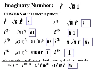
Im j ejθ 1 sinθ θ Re -1 1 cosθ -j Euler’s Identity • Appendix A reviews complex numbers Complex exponential (ejθ) is a point on the complex plane Euler’s equation Discussion #13 – Phasors
Phasors • Rewrite the expression for a general sinusoid signal: magnitude Angle (or argument) Complex phasor notation for the simplification: NB: The ejwt term is implicit (it is there but not written) Discussion #13 – Phasors
π π -ω ω Frequency Domain Graphing in the frequency domain: helpful in order to understand Phasors π[δ(ω – ω0) + δ(ω – ω0)] cos(ω0t) Time domain Frequency domain Discussion #16 – Frequency Response
3000 km 0.3 mm 0.3 mm 30 mm 300 km 30 mm 300 m 0.03Å 300Å 0.3 m 3 mm 30 km 3 mm 30 m 0.3Å 3 km 30Å 3 m 3Å … … 1017 Hz 1016 Hz 1012 Hz 1015 Hz 1011 Hz 1010 Hz 1014 Hz 1018 Hz 1013 Hz 1020 Hz 1019 Hz 105 Hz 104 Hz 109 Hz 108 Hz 107 Hz 106 Hz 103 Hz 102 Hz The Electromagnetic Spectrum Gamma rays Radio waves Ultraviolet Infrared Xray Microwaves wavelength Visible light
Phasors • Any sinusoidal signal can be represented by either: • Time-domain form: v(t) = Acos(ωt+θ) • Frequency-domain form: V(jω) = Aejθ = A θ • Phasor: a complex number expressed in polar form consisting of: • Magnitude (A) • Phase angle (θ) • Phasors do not explicitly include the sinusoidal frequency (ω) but this information is still important Discussion #13 – Phasors
+ – + – + – v1(t) v2(t) vs(t) ~ ~ ~ Phasors • Example 1: compute the phasor voltage for the equivalent voltage vs(t) • v1(t) = 15cos(377t+π/4) • v2(t) = 15cos(377t+π/12) Discussion #13 – Phasors
+ – + – + – v1(t) v2(t) vs(t) ~ ~ ~ Phasors • Example 1: compute the phasor voltage for the equivalent voltage vs(t) • v1(t) = 15cos(377t+π/4) • v2(t) = 15cos(377t+π/12) • Write voltages in phasor notation Discussion #13 – Phasors
+ – + – + – v1(t) v2(t) vs(t) ~ ~ ~ Phasors • Example 1: compute the phasor voltage for the equivalent voltage vs(t) • v1(t) = 15cos(377t+π/4) • v2(t) = 15cos(377t+π/12) • Write voltages in phasor notation • Convert phasor voltages from polar to rectangular form (see Appendix A) Discussion #13 – Phasors
+ – + – + – v1(t) v2(t) vs(t) ~ ~ ~ Phasors • Example 1: compute the phasor voltage for the equivalent voltage vs(t) • v1(t) = 15cos(377t+π/4) • v2(t) = 15cos(377t+π/12) • Write voltages in phasor notation • Convert phasor voltages from polar to rectangular form (see Appendix A) • Combine voltages Discussion #13 – Phasors
+ – + – + – v1(t) v2(t) vs(t) ~ ~ ~ Phasors • Example 1: compute the phasor voltage for the equivalent voltage vs(t) • v1(t) = 15cos(377t+π/4) • v2(t) = 15cos(377t+π/12) • Write voltages in phasor notation • Convert phasor voltages from polar to rectangular form (see Appendix A) • Combine voltages • Convert rectangular back to polar Discussion #13 – Phasors
+ – + – + – v1(t) v2(t) vs(t) ~ ~ ~ Phasors • Example 1: compute the phasor voltage for the equivalent voltage vs(t) • v1(t) = 15cos(377t+π/4) • v2(t) = 15cos(377t+π/12) • Write voltages in phasor notation • Convert phasor voltages from polar to rectangular form (see Appendix A) • Combine voltages • Convert rectangular back to polar • Convert from phasor to time domain NB: the answer is NOT simply the addition of the amplitudes of v1(t) and v2(t) (i.e. 15 + 15), and the addition of their phases (i.e. π/4 + π/12) Bring ωt back Discussion #13 – Phasors
Im + – + – + – v1(t) v2(t) vs(t) ~ ~ ~ π/6 Vs(jω) 14.49 Re 25.10 Phasors • Example 1: compute the phasor voltage for the equivalent voltage vs(t) • v1(t) = 15cos(377t+π/4) • v2(t) = 15cos(377t+π/12) Discussion #13 – Phasors
Load i1(t) Phasors of Different Frequencies Superposition of AC signals: when signals do not have the same frequency (ω) the ejωtterm in the phasors can no longer be implicit I + v – i2(t) NB: ejωt can no longer be implicit Discussion #13 – Phasors
R2 R1 + – vs(t) i1(t) Phasors of Different Frequencies Superposition of AC signals: when signals do not have the same frequency (ω) solve the circuit separately for each different frequency (ω) – then add the individual results Discussion #13 – Phasors
+ R2 – + R1 – + – vs(t) i1(t) Phasors of Different Frequencies • Example 2: compute the resistor voltages • is(t) = 0.5cos[2π(100t)] A • vs(t) = 20cos[2π(1000t)] V • R1 = 150Ω, R2 = 50 Ω Discussion #13 – Phasors
+ R2 – + R1 – + – vs(t) i1(t) i1(t) Phasors of Different Frequencies • Example 2: compute the resistor voltages • is(t) = 0.5cos[2π(100t)] A • vs(t) = 20cos[2π(1000t)] V • R1 = 150Ω, R2 = 50 Ω • Since the sources have different frequencies (ω1 = 2π*100) and (ω2 = 2π*1000) use superposition • first consider the (ω1 = 2π*100) part of the circuit • When vs(t) = 0 – short circuit + R2 – + R1 – Discussion #13 – Phasors
i1(t) Phasors of Different Frequencies • Example 2: compute the resistor voltages • is(t) = 0.5cos[2π(100t)] A • vs(t) = 20cos[2π(1000t)] V • R1 = 150Ω, R2 = 50 Ω • Since the sources have different frequencies (ω1 = 2π*100) and (ω2 = 2π*1000) use superposition • first consider the (ω1 = 2π*100) part of the circuit + R1|| R2 – Discussion #13 – Phasors
+ R2 – + R1 – + – + – vs(t) vs(t) i1(t) Phasors of Different Frequencies • Example 2: compute the resistor voltages • is(t) = 0.5cos[2π(100t)] A • vs(t) = 20cos[2π(1000t)] V • R1 = 150Ω, R2 = 50 Ω • Since the sources have different frequencies (ω1 = 2π*100) and (ω2 = 2π*1000) use superposition • first consider the (ω1 = 2π*100) part of the circuit • Next consider the (ω2 = 2π*1000) part of the circuit + R2 – + R1 – Discussion #13 – Phasors
+ R2 – + R1 – + – vs(t) i1(t) Phasors of Different Frequencies • Example 2: compute the resistor voltages • is(t) = 0.5cos[2π(100t)] A • vs(t) = 20cos[2π(1000t)] V • R1 = 150Ω, R2 = 50 Ω • Since the sources have different frequencies (ω1 = 2π*100) and (ω2 = 2π*1000) use superposition • first consider the (ω1 = 2π*100) part of the circuit • Next consider the (ω2 = 2π*1000) part of the circuit • Add the two together Discussion #13 – Phasors
i(t) i(t) i(t) + vR(t) – + vC(t) – + vL(t) – R C L + – + – + – + – Vs(jω) vs(t) vs(t) vs(t) ~ ~ ~ ~ I(jω) + VZ(jω) – Z Impedance Impedance: complex resistance (has no physical significance) • Allows us to use network analysis methods such as node voltage, mesh current, etc. • Capacitors and inductors act as frequency-dependent resistors Discussion #13 – Phasors
+ – Vs(jω) ~ Im I(jω) I + VZ(jω) – V Z Re Impedance – Resistors Impedance of a Resistor: • Consider Ohm’s Law in phasor form: Phasor Phasor domain NB: Ohm’s Law works the same in DC and AC Discussion #13 – Phasors
i(t) + vL(t) – L + – vs(t) ~ Impedance – Inductors Impedance of an Inductor: • First consider voltage and current in the time-domain NB: current is shifted 90° from voltage Discussion #13 – Phasors
i(t) Im + vL(t) – L + – + – Vs(jω) vs(t) V ~ ~ Re I(jω) -π/2 + VZ(jω) – I Z Impedance – Inductors Impedance of an Inductor: • Now consider voltage and current in the phasor-domain Phasor Phasor domain Phasor Discussion #13 – Phasors
i(t) + vC(t) – C + – + – Vs(jω) vs(t) ~ ~ I(jω) + VZ(jω) – Z Impedance – Capacitors Impedance of a capacitor: • First consider voltage and current in the time-domain Phasor Phasor Discussion #13 – Phasors
Im + – Vs(jω) ~ V I π/2 Re I(jω) + VZ(jω) – Z Impedance – Capacitors Impedance of a capacitor: • Next consider voltage and current in the phasor-domain Phasor domain Discussion #13 – Phasors
Im ωL ZL π/2 Re R + – + R – Vs(jω) ~ ZR -π/2 + C – + L – ZC I(jω) -1/ωC + VZ(jω) – Z Impedance Impedance of resistors, inductors, and capacitors Phasor domain Discussion #13 – Phasors
Im ωL ZL π/2 Re R + – Vs(jω) ~ ZR -π/2 ZC I(jω) -1/ωC + VZ(jω) – Z Impedance Impedance of resistors, inductors, and capacitors Phasor domain Not a phasor but a complex number AC resistance reactance Discussion #13 – Phasors
Im Im + R – + C – R Re ZR Re + C – -π/2 ZC -π/2 ZC -1/ωC -1/ωC Impedance Practical capacitors: in practice capacitors contain a real component (represented by a resistive impedance ZR) • At highfrequencies or high capacitances • ideal capacitor acts like a short circuit • At lowfrequencies or low capacitances • ideal capacitor acts like an open circuit Practical Capacitor Ideal Capacitor NB: the ratio of ZC to ZR is highly frequency dependent Discussion #13 – Phasors
Im Im + L – ωL ωL ZL ZL π/2 Re π/2 R Re + R – + L – ZR Impedance Practical inductors: in practice inductors contain a real component (represented by a resistive impedance ZR) • At low frequencies or low inductancesZR has a strong influence • Ideal inductor acts like a short circuit • At high frequencies or high inductancesZLdominates ZR • Ideal inductor acts like an open circuit • At high frequencies a capacitor is also needed to correctly model a practical inductor Ideal Inductor Practical Inductor NB: the ratio of ZL to ZR is highly frequency dependent Discussion #13 – Phasors
+ R – + Z – + C – Impedance • Example 3: impedance of a practical capacitor • Find the impedance • ω = 377 rads/s, C = 1nF, R = 1MΩ Discussion #13 – Phasors
+ Z – Impedance • Example 3: impedance of a practical capacitor • Find the impedance • ω = 377 rads/s, C = 1nF, R = 1MΩ + R – + C – Discussion #13 – Phasors
R1 L ZEQ R2 C Impedance • Example 4: find the equivalent impedance (ZEQ) • ω = 104 rads/s, C = 10uF, R1 = 100Ω, R2 = 50Ω, L = 10mH Discussion #13 – Phasors
R1 L ZEQ R2 C Impedance • Example 4: find the equivalent impedance (ZEQ) • ω = 104 rads/s, C = 10uF, R1 = 100Ω, R2 = 50Ω, L = 10mH Discussion #13 – Phasors
ZEQ1 ZEQ Impedance • Example 4: find the equivalent impedance (ZEQ) • ω = 104 rads/s, C = 10uF, R1 = 100Ω, R2 = 50Ω, L = 10mH R1 L NB: at this frequency (ω) the circuit has an inductive impedance (reactance or phase is positive) Discussion #13 – Phasors