Download
1 / 47
530 likes | 866 Vues
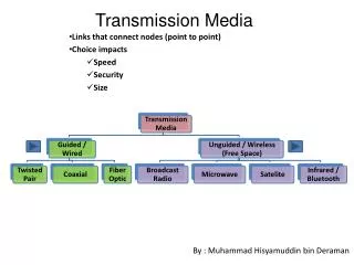
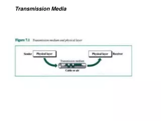
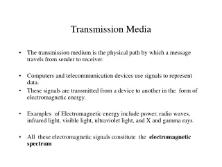
Transmission Media. Lecture By Mehran Mamonai Department of Telecommunication. Overview. Guided - wire Unguided - wireless Characteristics and quality determined by medium and signal For guided, the medium is more important

E N D
Transmission Media Lecture By Mehran Mamonai Department of Telecommunication
Overview • Guided - wire • Unguided - wireless • Characteristics and quality determined by medium and signal • For guided, the medium is more important • For unguided, the bandwidth produced by the antenna is more important • Key concerns are data rate and distance
Design Factors • Bandwidth • Higher bandwidth gives higher data rate • Transmission impairments • Attenuation • Interference • Number of receivers • In guided media • More receivers (multi-point) introduce more attenuation
Guided Transmission Media • Twisted Pair • Coaxial cable • Optical fiber
Frequency Range Typical Attenuation Typical Delay Repeater Spacing Twisted pair (with loading) 0 to 3.5 kHz 0.2 dB/km @ 1 kHz 50 µs/km 2 km Twisted pairs (multi-pair cables) 0 to 1 MHz 0.7 dB/km @ 1 kHz 5 µs/km 2 km Coaxial cable 0 to 500 MHz 7 dB/km @ 10 MHz 4 µs/km 1 to 9 km Optical fiber 186 to 370 THz 0.2 to 0.5 dB/km 5 µs/km 40 km Transmission Characteristics of Guided Media
Twisted Pair - Applications • Most common medium • Telephone network • Between house and local exchange (subscriber loop) • Within buildings • To private branch exchange (PBX) • For local area networks (LAN) • 10Mbps or 100Mbps
Twisted Pair - Pros and Cons • Cheap • Easy to work with • Low data rate • Short range
Twisted Pair - Transmission Characteristics • Analog • Amplifiers every 5km to 6km • Digital • Use either analog or digital signals • repeater every 2km or 3km • Limited distance • Limited bandwidth (1MHz) • Limited data rate (100MHz) • Susceptible to interference and noise
Near End Crosstalk • Coupling of signal from one pair to another • Coupling takes place when transmit signal entering the link couples back to receiving pair • i.e. near transmitted signal is picked up by near receiving pair
Unshielded and Shielded TP • Unshielded Twisted Pair (UTP) • Ordinary telephone wire • Cheapest • Easiest to install • Suffers from external EM interference • Shielded Twisted Pair (STP) • Metal braid or sheathing that reduces interference • More expensive • Harder to handle (thick, heavy)
UTP Categories • Cat 3 • up to 16MHz • Voice grade found in most offices • Twist length of 7.5 cm to 10 cm • Cat 4 • up to 20 MHz • Cat 5 • up to 100MHz • Commonly pre-installed in new office buildings • Twist length 0.6 cm to 0.85 cm • Cat 5E (Enhanced) –see tables • Cat 6 • Cat 7
Attenuation (dB per 100 m) Near-end Crosstalk (dB) Frequency (MHz) Category 3 UTP Category 5 UTP 150-ohm STP Category 3 UTP Category 5 UTP 150-ohm STP 1 2.6 2.0 1.1 41 62 58 4 5.6 4.1 2.2 32 53 58 16 13.1 8.2 4.4 23 44 50.4 25 — 10.4 6.2 — 41 47.5 100 — 22.0 12.3 — 32 38.5 300 — — 21.4 — — 31.3 Comparison of Shielded and Unshielded Twisted Pair
Category 3 Class C Category 5 Class D Category 5E Category 6 Class E Category 7 Class F Bandwidth 16 MHz 100 MHz 100 MHz 200 MHz 600 MHz Cable Type UTP UTP/FTP UTP/FTP UTP/FTP SSTP Link Cost (Cat 5 =1) 0.7 1 1.2 1.5 2.2 Twisted Pair Categories and Classes
Coaxial Cable Applications • Most versatile medium • Television distribution • Ariel to TV • Cable TV • Long distance telephone transmission • Can carry 10,000 voice calls simultaneously • Being replaced by fiber optic • Short distance computer systems links • Local area networks
Coaxial Cable - Transmission Characteristics • Analog • Amplifiers every few km • Closer if higher frequency • Up to 500MHz • Digital • Repeater every 1km • Closer for higher data rates
Optical Fiber - Benefits • Greater capacity • Data rates of hundreds of Gbps • Smaller size & weight • Lower attenuation • Electromagnetic isolation • Greater repeater spacing • 10s of km at least
Optical Fiber - Applications • Long-haul trunks • Metropolitan trunks • Rural exchange trunks • Subscriber loops • LANs
Optical Fiber - Transmission Characteristics • Act as wave guide for 1014 to 1015 Hz • Portions of infrared and visible spectrum • Light Emitting Diode (LED) • Cheaper • Wider operating temp range • Last longer • Injection Laser Diode (ILD) • More efficient • Greater data rate • Wavelength Division Multiplexing
Wavelength (in vacuum) range (nm) Frequency range (THz) Band label Fiber type Application 820 to 900 366 to 333 Multimode LAN 1280 to 1350 234 to 222 S Single mode Various 1528 to 1561 196 to 192 C Single mode WDM 1561 to 1620 185 to 192 L Single mode WDM Frequency Utilization for Fiber Applications
Wireless Transmission Frequencies • 2GHz to 40GHz • Microwave • Highly directional • Point to point • Satellite • 30MHz to 1GHz • Omnidirectional • Broadcast radio • 3 x 10¹¹ to 2 x 10¹⁴ • Infrared • Local
Antennas • Electrical conductor (or system of..) used to radiate electromagnetic energy or collect electromagnetic energy • Transmission • Radio frequency energy from transmitter • Converted to electromagnetic energy • By antenna • Radiated into surrounding environment • Reception • Electromagnetic energy impinging on antenna • Converted to radio frequency electrical energy • Fed to receiver • Same antenna often used for both
Radiation Pattern • Power radiated in all directions • Not same performance in all directions • Isotropic antenna is (theoretical) point in space • Radiates in all directions equally • Gives spherical radiation pattern
Parabolic Reflective Antenna • Used for terrestrial and satellite microwave • Parabola is locus of point equidistant from a line and a point not on that line • Fixed point is focus • Line is directrix • Revolve parabola about axis to get paraboloid • Cross section parallel to axis gives parabola • Cross section perpendicular to axis gives circle • Source placed at focus will produce waves reflected from parabola in parallel to axis • Creates (theoretical) parallel beam of light/sound/radio • On reception, signal is concentrated at focus, where detector is placed
Antenna Gain • Measure of directionality of antenna • Power output in particular direction compared with that produced by isotropic antenna • Measured in decibels (dB) • Results in loss in power in another direction • Effective area relates to size and shape • Related to gain
Terrestrial Microwave • Parabolic dish • Focused beam • Line of sight • Long haul telecommunications • Higher frequencies give higher data rates
Satellite Microwave • Satellite is relay station • Satellite receives on one frequency, amplifies or repeats signal and transmits on another frequency • Requires geo-stationary orbit • Height of 35,784km • Television • Long distance telephone • Private business networks
Broadcast Radio • Omnidirectional • FM radio • UHF and VHF television • Line of sight • Suffers from multipath interference • Reflections
Infrared • Modulate noncoherent infrared light • Line of sight (or reflection) • Blocked by walls • e.g. TV remote control, IRD port
Wireless Propagation • Signal travels along three routes • Ground wave • Follows contour of earth • Up to 2MHz • AM radio • Sky wave • Amateur radio, BBC world service, Voice of America • Signal reflected from ionosphere layer of upper atmosphere • (Actually refracted) • Line of sight • Above 30Mhz • May be further than optical line of sight due to refraction • More later…
Refraction • Velocity of electromagnetic wave is a function of density of material • ~3 x 10⁸ m/s in vacuum, less in anything else • As wave moves from one medium to another, its speed changes • Causes bending of direction of wave at boundary • Towards more dense medium • Index of refraction (refractive index) is • Sin(angle of incidence)/sin(angle of refraction) • Varies with wavelength • May cause sudden change of direction at transition between media • May cause gradual bending if medium density is varying • Density of atmosphere decreases with height • Results in bending towards earth of radio waves
Line of Sight Transmission • Free space loss • Signal disperses with distance • Greater for lower frequencies (longer wavelengths) • Atmospheric Absorption • Water vapour and oxygen absorb radio signals • Water greatest at 22GHz, less below 15GHz • Oxygen greater at 60GHz, less below 30GHz • Rain and fog scatter radio waves • Multipath • Better to get line of sight if possible • Signal can be reflected causing multiple copies to be received • May be no direct signal at all • May reinforce or cancel direct signal • Refraction • May result in partial or total loss of signal at receiver
Required Reading • Stallings Chapter 4