Download
1 / 23
230 likes | 420 Vues
ANKA Seminar. Ultra-low emittance for the CLIC damping rings using super-conducting wigglers. Yannis PAPAPHILIPPOU. October 8th, 2007. Outline. Overview of the CLIC Project CLIC damping rings design Design goals and challenges Energy Lattice choice and optics optimisation

E N D
ANKA Seminar Ultra-low emittance for the CLIC damping rings using super-conducting wigglers Yannis PAPAPHILIPPOU October 8th, 2007
Outline • Overview of the CLIC Project • CLIC damping rings design • Design goals and challenges • Energy • Lattice choice and optics optimisation • Circumference • Wiggler design and parameter scan • Final emittances including Intra-beam scattering • Chromaticity correction and dynamic aperture • Low emittance tuning in the presence of coupling • Summary and open issues M. Korostelev (PhD thesis, EPFL 2006) ANKA Seminar, Y. Papaphilippou
The CLIC Project • Compact Linear Collider : multi-TeV electron-positron collider for high energy physics beyond today's particle accelerators • Center-of-mass energy from 0.5 to 3 TeV • RF gradient and frequencies are very high • 100 MV/m in room temperature accelerating structures at 12 GHz • Two-beam-acceleration concept • High current “drive” beam, decelerated in special power extraction structures (PETS) , generates RF power for main beam. • Challenges: • Efficient generation of drive beam • PETS generating the required power • 12 GHz RF structures for the required gradient • Generation/preservation of small emittance beam • Focusing to nanometer beam size • Precise alignment of the different components ANKA Seminar, Y. Papaphilippou
Injector complex 30 m 30 m e- Main Linac e+ Main Linac e- BC2 e+ BC2 12 GHz 2.3 GV 12 GHz 2.3 GV 12 GHz, 100 MV/m, 21 km 12 GHz, 100 MV/m, 21 km 9 GeV 48 km maximum 3 TeV Base line configuration Booster Linac 6.6 GeV 3 GHz 360 m e+ BC1 e- BC1 10 m 10 m 3 GHz 162 MV 3 GHz 162 MV 2.424 GeV 360 m 2.424 GeV 360 m e+ DR e- DR e- PDR e+ PDR 2.424 GeV 2.424 GeV L. Rinolfi Injector Linac 2.2 GeV 1.5 GHz 150 m e-/e+ Target Laser Primary beam Linac for e- 2 GeV Pre-injector Linac for e+ 200 MeV Pre-injector Linac for e- 200 MeV DC gun Polarized e- DC gun Unpolarized e- 1.5 GHz 1.5 GHz 1.5 GHz 15 m 15 m 150 m
Damping ring design goals • Ultra-low emittance and high beam polarisation impossible to be produced by conventional particle source: • Ring to damp the beam size to desired values through synchrotron radiation • Intra-beam scattering due to high bunch current blows-up the beam • Equilibrium “IBS dominated” emittance should be reached fast to match collider high repetition rate • Other collective effects (e.g. e--cloud) may increase beam losses • Starting parameter dictated by design criteria of the collider (e.g. luminosity), injected beam characteristics or compatibility with the downstream system parameters (e.g. bunch compressors)
Ring energy • Choice dictated by spin tune (half integer) for maintaining high-spin polarisation • Frozen on early design stage • Advantage of lower energies: • For same equilibrium emittance i.e. smaller circumference and radiated power (cost), high momentum compaction (longitudinal stability). • Advantages of higher energy • For fixed damping fraction due to wigglers and wiggler peak field, i.e. easier magnetic design (lower main field) and smaller total wiggler length ANKA Seminar, Y. Papaphilippou
Lattice choice • Usually racetrack configuration with Theoretical Minimum Emittance (TME) arcs and damping wigglers in the straights • NLC DR was based on lattice with 32 TME arc cells and wigglers of 62m total length (A. Wolskiet al. 2003) • ILC has a large ring of more than 6km for accepting large number of bunches with reduced e-cloud effect • TME and FODO lattice considered (A. Wolskiet al. 2007)
CLIC damping ring layout ANKA Seminar, Y. Papaphilippou
TME arc cell • TME cell chosen for compactness and efficient emittance minimisation over Multiple Bend Structures (or achromats) used in light sources • Large phase advance necessary to achieve optimum equilibrium emittance • Very low dispersion • Strong sextupoles needed to correct chromaticity • Impact in dynamic aperture
Phase advance choice • Optimum horizontal phase advance of cells for minimising zero current emittance is fixed (284o for TME cells) • Vertical phase advance is almost a free parameter • First iteration based on lattice considerations, i.e. comfortable beta functions and relaxed quadrupole strengths and chromaticity • Low horizontal phase advance gives increased momentum compaction factor (high dispersion) but also chromaticity ANKA Seminar, Y. Papaphilippou
Phase advance with IBS Horizontal phase advance for minimum horizontal emittance with IBS, is found in an area of small horizontal beta and moderate dispersion functions (between 1.2-1.3π, for CLIC damping rings) Optimal vertical phase advance quite low (0.2π) The lowest longitudinal emittance is achieved for high horizontal and low vertical phase advances The optimal point has to be compromised due to chromaticity considerations and dynamic aperture optimisation ANKA Seminar, Y. Papaphilippou 11
Circumference Drifts + dipoles • Usually chosen big enough to accommodate number of bunches • Drift space increase essential for establishing realistic lattice, reserving enough space for instrumentation and other equipment • For constant number of dipoles (TME cells), zero equilibrium emittance is independent of circumference • Normalised emittance with IBS increases with circumference (no wigglers) • When dipole lengths increase with drifts, emittance grows due to increase of damping time (inversely proportional to radiation integral I2 which decreases with length) • When only drifts increase, smaller emittance growth due to increase of optics functions • Impact on chromaticity + dynamic aperture • Compensation may be achieved due to increase of bunch length with circumference (momentum compaction) Only Drifts Drifts + dipoles Only Drifts ANKA Seminar, Y. Papaphilippou
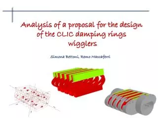
Damping wigglers • Damping wigglers are used to increase radiation damping and reduce the effect of IBS in order to reach target emittances • The total length of wigglers is chosen by its dependence with the peak wiggler field and relative damping factor • Damping factor increases for higher fields and longer wiggler occupied straight section • Relative momentum spread is independent of total length but increases with wiggler field ANKA Seminar, Y. Papaphilippou
Wigglers effect in emittance For fixed value of wiggler period, equilibrium emittance minimum for particular value of wiggler field By reducing total length, optimal values necessitate higher fields and lower wiggler periods Optimum values change when IBS included, necessitating higher fields Damping rings cannot reach 450nm with normal conducting wigglers ANKA Seminar, Y. Papaphilippou
Wigglers’ effect with IBS For higher wiggler field and smaller period the transverse emittance computed with IBS gets smaller The longitudinal emittance has a different optimum but it can be controlled with the RF voltage The choice of the wiggler parameters is finally dictated by their technological feasibility BINP PM wiggler BINP SC wiggler ANKA SC wiggler • The choice of the wiggler parameters is finally dictated by their technological feasibility. • Normal conducting wiggler of 1.7T can be extrapolated by existing designs • Super-conducting options have to designed, built and tested
Wiggler prototypes • Two wiggler prototypes • 2.5Τ, 5cm period, built by BINP • 2.7Τ,2.1cm period, built by ANKA • Aperture reduced for the more challenging design • Current density can be increased by using different conductor type • Short version to be installed and tested at ANKA (energy of 2.5GeV) • Lifetime of 8-10h for lower gap, enough for the beam tests ANKA Seminar, Y. Papaphilippou
RF voltage and frequency • The smallest transverse emittance is achieved for the lowest RF frequency and higher voltage, while keeping the longitudinal emittance below 5000 eV.m • Reversely the longitudinal emittance is increased for small RF frequency ANKA Seminar, Y. Papaphilippou
Average horizontal β function should be small enough for the wiggler period not to exceed the value producing efficient damping FODO cell structure chosen with phase advances close to 90o giving average β’s of around 4m and reasonable chromaticity Quad strength adjusted to cancel wiggler induced tune-shift Wiggler FODO cell 18
Non-linear dynamics • Two sextupole schemes considered • Two families / 9 families of sextupoles • Dynamic aperture is 9σxin the horizontal and 14σy in the vertical plane (comfortable for injection) • Wiggler effect should be included and optimised during the design phase
Coupling correction • Coupling effect of wigglers should be included in simulations • Correction with dispersion free steering (orbit and dispersion correction) • Skew quadrupole correctors for correcting dispersion in the arc and emittance minimisation • Iteration of dynamic aperture evaluation and optimisation after correction • In CLIC damping rings, the effect of vertical dispersion is dominant (0.1% of coupling and 0.25μm of dispersion invariant)
Bunch charge • Approximate scaling laws can be derived for a given damping ring design • For example, for the CLIC damping rings, the horizontal normalized emittance scales approximately as • The above relationship is even more exact when the longitudinal emittance is kept constant (around 5000 eV.m, in the case of the CLIC damping rings) • Vertical and longitudinal emittance are weakly dependent on bunch charge, and almost linear with each other ANKA Seminar, Y. Papaphilippou 21
Damping rings’ parameters • 2005: original ring • 2006a: super-conducting wiggler considered • 2006b: vertical dispersion included • 2007a: 12GHz structure • 2007b: reduced bunch population • 2007c: CLIC_G structure ANKA Seminar, Y. Papaphilippou CLIC PWG Y. Papaphilippou 22
Concluding remarks • Robust design of the CLIC damping rings, delivering target emittance with the help of super-conducting wigglers • Prototype to be built and tested in ANKA • Areas needing further optimisation • Pre-damping ring optics design • Collective effects including electron cloud • Realistic cell length and magnet design • Sextupole optimisation and non-linear dynamics including wiggler field errors ANKA Seminar, Y. Papaphilippou