Download
1 / 47
470 likes | 605 Vues
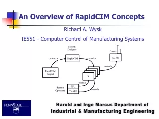
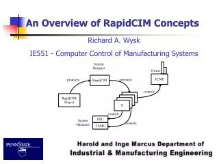
An Overview of RapidCIM Concepts. Richard A. Wysk IE551 - Computer Control of Manufacturing Systems. Agenda. Traditional Software Development Motivation for RapidCIM RapidCIM Concepts Equipment Level Models Message-based Part State Graphs Conclusions Resources. Introduction. Automated

E N D
An Overview of RapidCIM Concepts Richard A. Wysk IE551 - Computer Control of Manufacturing Systems
Agenda Traditional Software Development Motivation for RapidCIM RapidCIM Concepts Equipment Level Models Message-based Part State Graphs Conclusions Resources
Introduction Automated Flexible Manufacturing Cells/Shops Hardware System Control Software Programming Tools & Software Tools to assist in development of System Control Software Input Input ???? CAD Models etc. NC Programming Offline Robot Programming etc. ????
Traditional Control Software Development • In traditional “PLC-type” control, the control software is developed using the same planning, scheduling, and execution flow diagram.
Traditional Control Software Development • Planning (determining part routes) and scheduling (sequencing tasks) are built into the control software - Similar to a PLC ladder diagram. • Adding new parts or changing the scheduling rules require significant modifications to the control software • These changes must be done by the FMS vendor instead of the system operators
Motivation For RapidCIM • Most current FMS control implementations are customized • Lack of generic tools • Limitations in flexibility and reconfiguration • High cost of reliable software development • 2/3 rd of total expenditure is incurred during implementation phase, due to errors in software design • approx. 64% of the errors are made at the concept stage and only 36% are programming errors • On average, 50% or more of the software costs for flexible automation are related to control
Shop-floor control • Lack of emphasis on software development • Architectures do not provide sufficient detail • Software requirements have not been systematically analyzed to separate generic requirements from implementation-specific requirements • Functions performed are too tightly coupled • Tools to aid in the manufacturing system software development do not exist
Specific Tasks • Understand the control elements of a FMS • Develop theoretical foundations for FMS control, through use of formal models • Create generic model of control independent of implementation specifics • Automatic generation of control software for various controllers in the cell using the formal models • Create a FMS control software development methodology which can be implemented as a set of domain specific CASE tools
Need Software That is generic and hence reuseable Easily customized per installation Modular & modules being “plug compatible” Control Software Shop Floor Control Software Generic Implementation Specific Automatically Generated Hand Coded
Control Hierarchy • EQUIPMENT • Physical devices (NC machines, robots, AGV, ASRS, programmable fixtures, buffers, etc) • WORKSTATION • Integrated pieces of equipment • Robot tending a single machining center, along with requisite fixtures, sensors, etc. • Robot tending several machines • SHOP • Several integrated workstations, coupled by material transport workstations
Equipment Level • Each controllable equipment is viewed as comprising • Physical device controller (supplied with machine) • Equipment controller (typically a PC) • Generic Classes of Equipment • MP - Material Processor (NC machine, CMM) • MH - Material Handler (robot) • MT - Material Transporter (AGV, conveyor) • AS - Automated Storage Device
EQUIPMENT LEVEL (Cont) • Non Controllable equipment • BS - passive buffer storage devices • PD - passive devices • Ports (entry and exit of parts) • PO - ports • Equipment level controller • incorporates a device driver, that implements the equipment level functions (cycle start, download, etc) This is the implementation specific portion
Workstation Level • Workstation comprises • equipment (MP, MH, PO, BS, MT ....) • Types of Workstation • Processing workstation • Transport Workstation • Storage Workstation
Planning, Scheduling, and Execution • PlanningDetermining what tasks thesystem needs to perform • SchedulingSequencing planned tasks • ExecutionPerforming the scheduledtasks at the appropriatetime
Material Processor System Model Physical Configuration Physical Model
Material Handler System Model Physical Configuration Physical Model
Can this be implemented in a generic manner? • Custom specifics • Protocols • Communications
Message-based Part State Graph (MPSG) • An MPSG is a deterministic finite automaton representing the processing protocol for a part. • An MPSG state provides information about the current processing state of the part that is needed to determine the behavior on subsequent events. • State transitions are caused by receiving messages about the part and by performing functions specified by the scheduler.
Mealy Machine • A Mealy machine is essentially a finite automaton with output. Formally, a Mealy machine M is defined as follows: • So, a Mealy machine is a finite state automaton in which an output (defined by and ) is generated during state transitions.
MPSG Characteristics • Explicitly separate scheduling from execution. • Extensible at multiple levels to facilitate software development • Generic MPSG can be used unmodified. • Extraneous transitions can be removed. • Specified messages and tasks can be rearranged. • New messages and tasks can be specified. • Execution portion of the control software is automatically generated from the MPSG description.
Storage Class • Provides basic database functions for the controller • Parts are tracked based on their location in the shop, state, and the workstation and equipment level device to which they are assigned. • Objects within the storage class • Parts • Slots - Corresponding to physical locations • Entities - Lower level controllers in the control hierarchy
Controller Class • Embellishes the storage class with the data structures necessary for control.
Equipment Class • Specializes the controller class so that the instantiated objects interact directly with a piece of equipment • Not “Equipment Objects” in the system. Rather the equipment class is further partitioned based on the behavior of the individual pieces of equipment. • Material Processors (MP) • Material Handlers (MH) • Automated Storage Devices (AS) • Material Transporters (MT)
Software Generation • Generation software has been developed in C++ for use in DOS, OS/2, ULTRIX, AIX, UNIX and Windows operating system environments. • Components of the generation system • MPSG Builder • Controller Class • MPSG Class • Communications Class (IOMUX for CIM lab implementation) • Generic equipment descriptions and functions • MPSG • Scheduler • Task action functions
Communication • Controller to device • Controller to controller • Controller to database • Controller to Messaging
Communications - continued • IOMUX • 1995 based system that connected all of the computers • Router • 1997 based system that uses a single device to route all messages
IOMUX (I/O Multiplier) • Facilitates the interprocess transfer of data in a consistent manner independent of the hardware/operating systems of the components. • System components can be reconfigured without recompilation by modifying an ASCII configuration file representing the route map (default.map).
Platform/domain • Formerly implemented on the following platforms: • DOS • RS-232 Serial • TCP/IP using Watt TCP • OS/2 • TCP/IP • Shared queues (IPC) • UNIX - TCP/IP • DEC ULTRIX • IBM AIX • SGI
Current Implementation • Windows NT/ Windows 2000 serves as the core for the system. • Arena 3 or 4 is used as message generation for the Execution system • Router – communication • Access - database
Controller Tasks • Physical Model actions/tasks become tasks issued by simulation • Simulation - issues a “pick” through a message placed in the task initiation queue • Big Executor • explodes the “pick” task into various messages that are send to the individual controllers and co-ordinates their actions based on the responses • returns a “pick_done” message to the simulation in the task completion queue
Conclusions • Traditional Control Software generation issues • Concept of RapidCIM • Separation of Planning and Execution • Physical models for equipment classes • Workstation and shop level controllers
What Next? • Manufacturing Architectures • RapidCIM • Simulation-based Control NEXT! • Implementation Issues
Resources • Joshi, S. B., Mettala, E. G., Smith J. S., and Wysk, R. A., “Formal models for control of flexible manufacturing cells: physical and system model”, IEEE Transactions on Robotics and Automation, v11, n4, Aug, 1995 IEEE, Piscataway, NJ, USA, p 558-570. • Joshi, S., J. Smith, R. Wysk, B. Peters, and C. Pegden, "Rapid-CIM: An Approach to Rapid Development of Control Software for FMS Control", 27th CIRP International Seminar on Manufacturing Systems, Ann Arbor, MI, May, 1995. • Mettala, E. G., “Automatic generation of control software in computer-integrated manufacturing”, Ph.D. Dissertation, Department of Industrial and Manufacturing Engineering, Pennsylvania State University, University Park, PA 16802, 1989.
Resources • Qui, R. B., “Modeling and Control of a flexible manufacturing system using deterministic finite capacity automata”, Ph.D. Dissertation, Department of Industrial and Manufacturing Engineering, Pennsylvania State University, University Park, PA 16802, 1996. • Qui, R. B. and Joshi, S. B., “Deterministic finite capacity automata: a solution to reduce the complexity of modeling and control of automated manufacturing systems”, Proceedings of the 1996 IEEE International Symposium on Computer-Aided Control System Design, Sep 15-18 1996, Dearborn, MI, USA, p 218-223 • Qui, R. B. and Joshi, S. B., “A Structured Adaptive Supervisory Control Methodology doe Modeling the Control of Discrete Event Manufacturing” IEEE Transactions on Systems, Man, and Cybernetics, vol. 29, no. 6, 1999, pp. 573-586