Moving Laser Heater
Moving Laser Heater. Introduction. Lasers are commonly used to achieve precision heating or welding. The beam often moves over the surface of the substrate.

Moving Laser Heater
E N D
Presentation Transcript
Introduction • Lasers are commonly used to achieve precision heating or welding. The beam often moves over the surface of the substrate. • One difficulty with modeling a laser heat source is the fact that the beam is very narrow (nm-mm). Another is that the laser has a certain penetration depth which may be important. • The purpose of this model is to demonstrate how to model a moving depth-distributed line heat source in COMSOL Multiphysics using a 3D-1D coupling. • The results show that the penetration depth plays an important role in the heating process.
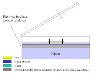
Model Definition – Geometries • The model is based on a 3D energy balance coupled to a 1D model of the laser intensity in the depth of the substrate. thickness: 1 mm 3D: 1D (thickness):
Model Definition – Equations • In the 3D domain an ordinary energy balance is used, for example using a Conduction application mode. • In the 1D domain a Weak application mode is used. The equation is: • (Ix-k_abs*T*I)*I_test+I*P_in*T_test => • General transformation Extrusion Coupling is used to couple the moving laser source to the energy balance. • Transformation: x=r*(sin(w*t), y=r*cos(w*t), z=x2 • Results in a line heat source, xy-dimension limited by one element in the 3D geometry. • A very good representation of a laser heat source.
Model Definition – Parameters & Boundary Conditions • Parameters: • kT(silicon)=(163,163,1) • P_in (laser)=100 W • 3D energy balance BCs: • Isolating conditions on all boundaries • 1D intensity model BCs: • x=1e-3, I =1 (incoming laser intensity=1) • x=0, zero flux • The coupling variable causes a heat souce to occur in the 3D model: • QT=I*P_in_laser
Model Definition – Mesh, Solver • 2D triangular mesh is extruded to achieve hex-elements. • Advantages: • control of element thickness • Mesh finer along laser track => reduced mesh size and improved speed • 3144 elements • 2175 DOFs • Solver: • Solution form Weak • Time dependent with UMFPACK • Solution time: approx 20 sec (on 1.6 GHz PC-laptop)
Results – local temperature in solid • Local temperature distribution within the solid at the laser position. • Show Movie of T=f(t)
Results – local temperature at surface • Local temperature distribution along the laser beam track on the incident surface
Results – Intensity distribution • Laser intensity distribution in the depth of the sample at t=1sec. • The laser is fully absorbed - approximately 400 mm into the silicon sample.