Download
1 / 33
330 likes | 435 Vues
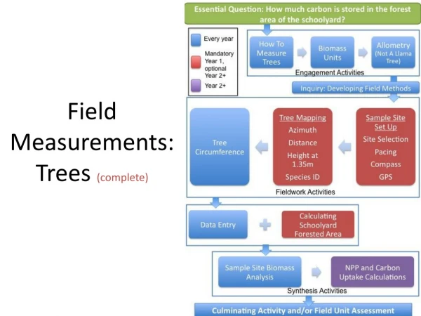
Field measurements of QEA magnets at KEK. Mika Masuzawa May 30, 2006. Contents. Purpose of the measurements at KEK Measurement system IHEP KEK Preliminary data Comparison between KEK and IHEP B’L (integrated field strength) Sextupole component Schedule.

E N D
Field measurements of QEA magnets at KEK Mika Masuzawa May 30, 2006
Contents • Purpose of the measurements at KEK • Measurement system • IHEP • KEK • Preliminary data • Comparison between KEK and IHEP • B’L (integrated field strength) • Sextupole component • Schedule
Purpose of the measurements at KEK Field measurements are necessary to spot a bad magnet as quickly as possible so that feedback to the production line can be made. • Measurements on site (IHEP) were very important. Why repeat the measurements at KEK? • B’L calibration. • Magnetic center evaluation when aligned by the alignment base. • Others
Why measure @KEK 1. B’L calibration • Both IHEP and KEK use a harmonic coil system. A signal like that in the figure is obtained each rotation. FFT of the waveform gives the amplitude and phase of each multipole component. • IHEP used a Hall probe mapping to translate the FFT amplitude into B’L [T]. This is needed to confirm that the magnets can produce a strong enough field at the max. current (150 A). • However, in the actual beam commissioning, it is important that the magnet strength in the extraction beam line (the new ATF2 beam line) and that of the ATF ring are consistent. Waveform from KEK system Originally, I was thinking of measuring a couple of IHEP magnets and one ATF magnet and scale them.
Why measure @KEK 1. B’L calibration -problems It turned out that the IHEP measurements of B’L have rather poor repeatability. The same magnet shows different strengths on different measurements by a few tenths of a %. So we decided to just measure all of the magnets in the 1st batch.
Why measure @KEK 2. Magnetic center when alignment base is used • IHEP did not use the alignment base when aligning a magnet to the harmonic system. • We will use the alignment base for the actual installation. • Magnetic center of the quadrupole field should be re-evaluated for the case (B).
Measurement system at IHEP Mechanical bearing Align the magnet to the measurement system using the magnet bore. Room temperature & cooling water temperature were not controlled. Electronics have to be turned off at lunch time & at night.
Measurement system at KEK Ceramic coil for rigidity, smaller thermal expansion Bobbin is made of Macor. Air bearing, for smoother rotation
Room & cooling water temperature controlled Air temp 0.5 degree Ignore this green line ~3 days Water temp to the building 1 degree Inlet water temp Monitor by K. Egawa
Measured the same #4 “reference” magnet on different days. IHEP B’L measurement Rather poor reproducibility ~0.5% !!!
Improvements made by IHEP • IHEP amd KEK exchanged opinions on how to improve the stability of the measurement system at IHEP. • IHEP made a wooden box to cover the system. • The data seem to have become more stable with the wooden box. • But some magnets had been measured already for shipping to Japan so we needed to re-measure them anyway. • We may not need to measure the newly arriving magnets (2nd batch).
IHEP Accelerator Center Stability/Reproducibility of the Rotating Coil Measurement system Magnet Group Li.LI, Zhang jc,Yin bg April, 03, 2006 LLI@mail.ihep.ac.cn
Reproducibility test on ATF2-04# at I=100 A(with wood room) • To Improve magnet measurement Environmental conditions, • we made a small wood room to cover the whole magnet, there is a window on the wood room, it can measure the temp. Magnet Group Li.LI, Zhang jc,Yin bg April, 03, 2006 LLI@mail.ihep.ac.cn
Problemes: 1.Vary of the b1 amplitude after re-alignment. Conclusion: • The higher multipole components are reproducibility. • Magnetic center are stably with wood room. • b2 amplitude are stably during per day. Magnet Group Li.LI, Zhang jc,Yin bg April, 03, 2006 LLI@mail.ihep.ac.cn
Preliminary data • A newly fabricated coil arrived at the end of March. • Some modification was made in April. • Assembly of the measurement system, including interlocks, was finished in early May. • Evaluation of the system in May. • Started measuring the QEA magnets in mid-May. • The data you see now are preliminary.
Repeatability of B’L Max. 150 A for “high current” group magnets. One measurement consists of a 5-loop standardization and measurement from low current. At each current data are taken three times. This is more or less the same as at IHEP.
Repeatability of B’L at different currents B’L(2nd)/B’L(1st) vs current QEA03 (May17) I(A)
Repeatability of B’L at different currents QEA07 (May19)
Repeatability of B’L at different currents QEA08 (May23)
Repeatability of B’L at different currents QEA11 (May12 and May15)
B’L measurement at KEK • System is stable. • Standardization guarantees desired field within a few x 10-4.
Comparison of IHEP and KEK measurements Should be on this line.
B’L distribution Usually we get Gaussian dist. But the IHEP QEA magnets do not show a Gaussian distribution. Why?
Thin liner insertion to adjust the sextupole component Example For #7 magnet 0.11 mm liner between #3 and #4 and 0.16 mm liner between #1 and #4
B’L as a function of liner thickness IHEP meas. KEK meas. Liner insertion makes the bore larger, resulting in a weaker field. KEK measurement shows a stronger correlation between the field Strength (B’L) and the liner thickness.
Multipole components, especially sextupole components • Both IHEP and KEK use a bucking coil configuration to evaluate the sextupole components, though the bucking ratio is different. • IHEP used digital bucking while KEK uses analog bucking. • KEK bucking configuration: additional coil mounted in the same plane as the main coil, connected in series (analog bucking) to reject quadrupole and dipole signals.
KEK multipole measurements with bucking coil (Preliminary) • Statistical errors are small. • Repeatability is good. Systematic error needs to be evaluated. Sextupole component
Sextupole component comparison between IHEP and KEK measurements #9,#10  magnets are not “shim” corrected. KEK measurement shows a lower sextupole component. Lower systematic errors? (I hope) Try to understand the systematics. In any case, avoid using #9, #12,,, magnets in critical places.
Magnetic center • IHEP data can not be used, as mentioned earlier, since the alignment base was not used for the field measurements. • KEK data are there along with B’L and higher multipoles. • But I have not digested the results yet so will show them next time.
Schedule • Will finish measuring the magnets in the 1st batch. • How about the magnets in the 2nd batch? • Check the reproducibility of the field after separating the top half of the magnet from the bottom half (needed when installing the vacuum pipe). • IHEP did this test already but we will do it again here, partially to practice how to reassemble the magnets. • Will summarize the results, including; • Magnetic center, dependence on the field strength,,, • Median plane (quadrupole phase) • other • Will measure one ATF magnet in the ring to scale the new ATF2 magnets at some point.
Problems we found • Target hole • Too big on #2 magnet • Too small (the target would not fit) on two magnets. • Bolts that hold the coils are magnetic (probably iron!).
6 bolts/coil = 24 bolts These are stainless bolts