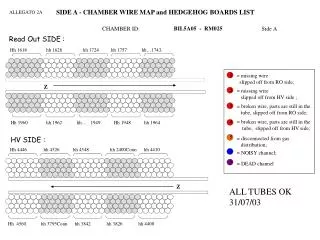

AET-2006 Reading 2A
E N D
Presentation Transcript
Pre My R eading on Acoustic Emission Testing 2016-02 For my ASNT Level III Examination on coming 2016 August. 22ndJune 2016 Fion Zhang/ Charlie Chong
Acoustic Emission Testing Fion Zhang/ Charlie Chong
Acoustic Emission Testing Charlie Chong/ Fion Zhang
Acoustic Emission Testing Charlie Chong/ Fion Zhang
Fion Zhang at St Petersburg 22ndJune 2016 Charlie Chong/ Fion Zhang
SME- Subject Matter Expert http://cn.bing.com/videos/search?q=Walter+Lewin&FORM=HDRSC3 https://www.youtube.com/channel/UCiEHVhv0SBMpP75JbzJShqw Charlie Chong/ Fion Zhang
http://www.yumpu.com/zh/browse/user/charliechong http://issuu.com/charlieccchong http://independent.academia.edu/CharlieChong1 Charlie Chong/ Fion Zhang
Charlie Chong/ Fion Zhang http://greekhouseoffonts.com/
The Magical Book of Tank Inspection ICP Charlie Chong/ Fion Zhang
ASNT Certification Guide NDT Level III / PdM Level III AE - Acoustic Emission Testing Length: 4 hours Questions: 135 1 Principles and Theory • Characteristics of acoustic emission testing • Materials and deformation • Sources of acoustic emission • Wave propagation • Attenuation • Kaiser and Felicity effects, and Felicity ratio • Terminology (refer to acoustic emission glossary, ASTM 1316) Charlie Chong/ Fion Zhang
2 Equipment and Materials • Transducing processes • Sensors • Sensor attachments • Sensor utilization • Simulated acoustic emission sources • Cables • Signal conditioning • Signal detection • Signal processing • Source location • Advanced signal processing • Acoustic emission test systems • Accessory materials • Factors affecting test equipment selection Charlie Chong/ Fion Zhang
3 Techniques • Equipment calibration and set up for test • Establishing loading procedures • Precautions against noise • Special test procedures • Data displays 4 Interpretation and Evaluation • Data interpretation • Data evaluation • Reports 5 Procedures 6 Safety and Health 7 Applications • Laboratory studies (material- characterization) • Structural applications Charlie Chong/ Fion Zhang
References & Catalog Numbers NDT Handbook, Second Edition: Volume 5, Acoustic Emission Testing Catalog Number 130 Acoustic Emission: Techniques and Applications Catalog Number 752 Charlie Chong/ Fion Zhang
数字签名 者:Fion Zhang DN:cn=Fion Zhang, o=Technical, ou=Academic, email=fion_zhang @qq.com, c=CN 日期:2016.07.01 12:35:01 +08'00' Charlie Chong/ Fion Zhang
闭门练功 Charlie Chong/ Fion Zhang
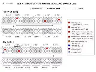
R eference Standards: ASTM: E 569 – Acoustic Emission Monitoring of Structures During Controlled Stimulation E 650 – Guide for Mounting Piezoelectric Acoustic Emission Sensors E 750 – Practice for Characterizing Acoustic Emission Instrumentation ASTM E 749-96 is a standard practice of AE monitoring of continuous welding. ASTM E 1932 for the AE examination of small parts ASTM E1419-00 for the method of examining seamless, gas-filled, pressure vessels. Charlie Chong/ Fion Zhang
API: RP 575 – Guidelines and Methods for Inspection of Existing Atmospheric and Low- Pressure Storage Tank. ST 307 – An Engineering Assessment of Acoustic Methods of Leak detection in Aboveground Storage tanks. ST 322 – An Engineering Evaluation of Acoustic Methods of Leak Detection in Aboveground storage Tank. ST 325 – An evaluation of a Methodology for the detection of Leaks in Aboveground Storage Tank. Charlie Chong/ Fion Zhang
R eading#1 Charlie Chong/ Fion Zhang
Introduction to Acoustic Emission Integrity Diagnostics Diagnostic Acoustic Emission Solutions for Safety and Performance http://www.idinspections.com/?page_id=126 Charlie Chong/ Fion Zhang
1.0 Introduction Acoustic emission is an amazing, promising and challenging subject of the modern technology and science. It is a well known from everyday life phenomenon: sound of breaking glass, falling tree, cracking ice are some examples of fracture sound we may hear from different objects subjected to stress. Scientifically defined, acoustic emission is a phenomenon of sound and ultrasound wave generation by materials that undergo deformation and fracture processes (Figure 1). Sources generating AE in different materials are unique. For examples, in metals, primary macroscopic sources are crack jumps, processes related to plastic deformation development and fracturing and de-bonding of inclusions. Quantitative and qualitative characteristics of acoustic emission waves, generated by sources of different nature depend directly on material properties and environmental factors. http://www.idinspections.com/?page_id=126 Charlie Chong/ Fion Zhang
Figure 1. Acoustic emission due to crack growth in a solid material under stress. http://www.idinspections.com/?page_id=126 Charlie Chong/ Fion Zhang
Leaks, friction, knocks, chemical reactions, changes of size of magnetic domains are other examples of sources generating acoustic emission waves. These sources belong to another, secondary class of acoustic emission that is usually distinguished from the primary class of sources related to deformation and fracture development. Understanding the nature of emitted sound, characteristics of sounds and what they represent, can be used for development of useful technological solutions in non-destructive testing, material studies, control of production, medical examinations, analysis of chemical reactions and many other fascinating applications. Presentation of fundamentals of the acoustic emission science and technology and its unique applications is the goal of this article. http://www.idinspections.com/?page_id=126 Charlie Chong/ Fion Zhang
2.0 The physical nature of the phenomenon Understanding the physical nature of acoustic emission in different materials is a cornerstone in the development of the acoustic emission technology. The success and the depth of the technology capabilities depend on the ability to determine the interconnection between characteristics of acoustic emission and sources it generated. However, establishing such interconnection for different materials and structures is a real scientific and technological challenge. http://www.idinspections.com/?page_id=126 Charlie Chong/ Fion Zhang
2.1 Material sources of acoustic emission The goals of acoustic emission examinations in industrial applications today, are detection, location and assessment of flaws in structures made of metal, concrete or composites. In these materials, fracture development in form of crack propagation is a primary source of acoustic emission. Elementary crack jumps under static or dynamic loads are followed by a rapid release of energy. A part of this energy is released in form of stress waves as a result of fast redistribution of a stress field at the crack top. The stress waves generated are elastic waves mostly but inelastic waves can be generated also when stresses exceed yield limit. This occurs, for example, at the plastic zone of a crack developing in a ductile metal. http://www.idinspections.com/?page_id=126 Charlie Chong/ Fion Zhang
Other primary sources of acoustic emission in materials that undergo fracture are: Plastic deformation development and fracturing of hard inclusions in metals; Fiber breakage, matrix cracking and delamination in composites; Aggregate fracture, voids closure and etc. in concrete. 2.2 Non-material secondary sources of acoustic emission Acoustic emission equipment is capable of detecting and analyzing acoustic emission sources of non-material origin, for instance, mechanical sources of friction, knocks, leaks and so on. There are multiple applications in which acoustic emission technology is used for revealing leaks, machinery health monitoring, detection of dynamic stress events in structures and other using these capabilities. http://www.idinspections.com/?page_id=126 Charlie Chong/ Fion Zhang
2.3 Wave propagation Acoustic emission wave propagation out of the source it generated over the structure is always a complex mechanical puzzle. Waves of different types propagate at different velocities and with different oscillation directions. Moreover, passing through a medium, waves undergo multiple changes due to attenuation, dispersion, diffraction, scattering, reflection from boundaries, interaction with reflections and other. In those applications, where it is possible either analytically or numerically describe wave propagation, it is possible to achieve a greater accuracy in the source location and it characterization. For example, in anisotropic materials, an accurate location is possible when an effective wave velocity is incorporated in a location algorithm as function of a propagation angle. Note: Anisotropic materials Anisotropy is the property of being directionally dependent, as opposed to isotropy, which implies identical properties in all directions. It can be defined as a difference, when measured along different axes, in a material's physical or mechanical properties (absorbance, refractive index, conductivity, tensile strength, etc.) An example of anisotropy is the light coming through a polarizer. Another is wood, which is easier to split along its grain than against it http://www.idinspections.com/?page_id=126 Charlie Chong/ Fion Zhang
2.4 Qualitative types of acoustic emission There are two distinct qualitative types of acoustic emission: burst and continuous. Burst is a type of emission related to individual events occurring in a material that results in discrete acoustic emission signals. Continuous is a type of emission that related to time overlapping and/or successive emission events from one or several sources that results in sustained signals. http://www.idinspections.com/?page_id=126 Charlie Chong/ Fion Zhang
Detection, ability to distinguish and analyze signals resulting from both emission types is important for many acoustic emission applications. For example, in ductile metals most of the energy expended on fracture processes goes to development of a plastic deformation, which normally accompanied by continuous acoustic emission. This is the reason why, normally flaws at their early stages in ductile metals can be detected mostly by use of continuous emission. Also, reliable detectability of specific flaws like stress corrosion cracking and creep are depend on detection and analysis of continuous acoustic emission. At the same time, there are flaws or conditions that can be detected by burst acoustic emission, like fracture of non-metallic inclusions, breakage of corrosion products, crack jumps in brittle or at advance stages in ductile metals and other. http://www.idinspections.com/?page_id=126 Charlie Chong/ Fion Zhang
Continuous Acoustic Emission fracture processes of a plastic deformation early stages in ductile metals, stress corrosion cracking and creep Burst Acoustic Emission fracture of non-metallic inclusions, (& brittle materials) breakage of corrosion products, crack jumps in brittle or fracture processes of a plastic deformation at advance stages in ductile metals and other. Charlie Chong/ Fion Zhang
Continuous Acoustic Emission fracture processes of a plastic deformation early stages in ductile metals, stress corrosion cracking and creep Burst Acoustic Emission fracture of non-metallic inclusions, (& brittle materials) breakage of corrosion products, crack jumps in brittle or fracture processes of a plastic deformation at advance stages in ductile metals and other. Charlie Chong/ Fion Zhang
Stress Corrosion Cracking - Metallic Corrosion Background The effects of residual and applied stresses and corrosive environments in service are closely interrelated. The more highly stressed (higher energy) regions of a metal will become anodic and corrosive cells will be set up due to differences in local stress levels. Cold worked regions, for example tube or sheet bends and cut edges, will be corroded in preference to uniform parts of sections in the same way that grain boundaries are attacked more than grain interiors on the microscopic scale. Stress Corrosion Cracking (SCC) Defined The combined effects of stress and corrosion can result in a special type of failure known as Stress Corrosion Cracking (SCC). This arises under a particular set of circumstances for a given alloy: specific alloy condition plus specific corrosive media and sufficient local tensile stress. Chloride induced cracking of stainless steels, caustic cracking of plain carbon steels and ammonia damage to copper alloys are typical examples of this problem. The mechanism of SCC is shown as a simple representation in Figure 1. http://www.azom.com/article.aspx?ArticleID=102 Charlie Chong/ Fion Zhang
Figure 1. Schematic view of Stress Corrosion Cracking (SCC) and corrosion fatigue cracking http://www.azom.com/article.aspx?ArticleID=102 Charlie Chong/ Fion Zhang
SCC is believed to be nucleated at pitting damage sites and develops under the action of local tensile stresses as a highly branched network of fine cracks. At each crack tip the combined action of the tensile stress and specific ions in the corrosive media cause continual crack propagation with little evidence of local deformation. In austenitic stainless steels, for example, warm chloride solutions in the presence of residual tensile stress can lead to cracking. SCC tendency is slight in low Ni ferritic and martensitic grades but is severe in the 8-10% Ni austenitic steels. Duplex stainless steels have greater SCC resistance than austenitic since the duplex microstructure helps to inhibit the growth of SCC cracks, which tend to be deflected or arrested at austenite-ferrite interfaces. Maximum resistance is obtained with 50/50 austenite-ferrite microstructures and the dispersion of the two phases should be as fine as possible. The increased interest in the duplex grades stems not only from their high pitting and SCC resistance but also from their higher proof stress level which offers savings in material and weight over austenitic http://www.azom.com/article.aspx?ArticleID=102 Charlie Chong/ Fion Zhang
When does SCC occur? Stress corrosion cracking presents an especially difficult problem, since not only is it highly localised but it can occur in environments that are merely mildly corrosive to the material. The damaging concentration of the harmful ions in that environment may be quite small and difficult to detect and, even in the absence of applied stress, residual stresses in a structure can often be of a sufficiently high level to cause SCC and failure in service. In a given situation the time of exposure needed to cause SCC failure depends on the stress intensity at any pre-existing or developed crack tip. The concentration of stress at the tip of a sharp crack or flaw can be quantified in terms of the Stress Intensity Factor, K1. It determines the growth rate of SCC cracks for a specific alloy environment combination. http://www.azom.com/article.aspx?ArticleID=102 Charlie Chong/ Fion Zhang
Catastrophic failure of a component will occur when this factor reaches a critical value, the Fracture toughness of the material, K1C. This enables the determination of allowable defect size in design to avoid failure under given loading conditions. Below a threshold value of K1, called K1SCC, growth of a crack by SCC is not expected, but above this value the initial SCC growth rate increases with increasing K1, called stage 1 cracking, Figure 2. http://www.azom.com/article.aspx?ArticleID=102 Charlie Chong/ Fion Zhang
Figure 2. Growth rate of SCC cracks. http://www.azom.com/article.aspx?ArticleID=102 Charlie Chong/ Fion Zhang
Figure 2. Growth rate of SCC cracks. http://www.azom.com/article.aspx?ArticleID=102 Charlie Chong/ Fion Zhang
In stage 2, the crack growth rate is independent of K1and depends instead on the corrosive environment and temperature. During stage 2 growth, K1 continues to increase and this leads to the rapid acceleration of the crack in stage 3, and final fast fracture when K1 reaches K1Cwhich is the Fracture Toughness of the material. The higher the value of K1SCCunder given conditions, then the greater is the expected SCC resistance, but some materials do not appear to have a threshold resistance. http://www.azom.com/article.aspx?ArticleID=102 Charlie Chong/ Fion Zhang
Stress Corrosion Cracking Charlie Chong/ Fion Zhang
2.5 Acoustic emission and loading conditions Flaws are developing in materials under stress, not necessarily dynamic and/or due to exposure to different environmental conditions. Since acoustic emission is accompanying fracture processes, it is essential for the success of acoustic emission examination to learn about common flaws existing in the structure been examined and operational and stress conditions that may cause flaw origination and development. Once these factors are established, a procedure for performing AE examination can be developed. The fundamental principal of such procedure is to perform examination under the real or simulating real loading conditions that cause flaw origination and development. For example, if it is known that a thick pipe suffers from a thermal fatigue due to a large temperature gradient, it can be ineffective to examine this pipe under hydraulic pressure and ambient temperature conditions, simply because the stress distribution will be different and flaw may not develop and consequently will not actively emit acoustic emission during the test. Sometimes, it is necessary to perform a test under various operational and stress condition in order to detect and evaluate different possible types of flaws. http://www.idinspections.com/?page_id=126 Charlie Chong/ Fion Zhang
2.6 Application of the acoustic emission method as a diagnostic tool for assessment of structural integrity Application of the acoustic emission as a diagnostic method, structural integrity assessment tool is possible when a qualitative or quantitative relationship between detected acoustic emission and material condition is established for a specific material and structure. ■ There are two major approaches to achieve this goal: Determining experimentally a characteristic set (fingerprints) of acoustic emission parameters and their characteristics that uniquely describe a material condition, fracture stage, flaw type and etc. For example, to find acoustic emission characteristic fingerprints of concrete cracking and rebar corrosion. http://www.idinspections.com/?page_id=126 Charlie Chong/ Fion Zhang
■ Establishing a theoretical relationship between acoustic emission parameters and their characteristics and material properties, fracture mechanics parameters and etc. For example, establishing relationship between acoustic emission energy and J-integral value of a crack. Many works in developing both approaches were done for different structures and materials, for example standard test methods for evaluation of pressure vessel condition or models interconnecting acoustic emission and fracture mechanics parameters like plastic deformation model, fatigue crack model and other described in [1]. http://www.idinspections.com/?page_id=126 Charlie Chong/ Fion Zhang
3.0 The technology 3.1 Sensors Acoustic emission sensor is a device that transforms a local dynamic material displacement produced by a stress wave to an electrical signal. AE sensors are typically piezoelectric sensors with elements maid of special ceramic elements like lead zirconate titanate (PZT). These elements generate electric signals when mechanically strained. Other types of sensors include capacitive transducers, laser interferometers. Selection of a specific sensor depends on the application, type of flaws to be revealed, noise characteristics and other factors. Typical frequency range in AE applications varies between 20 kHz and 1 MHz. There are two qualitative types of sensors according to their frequency responds: resonant and wideband sensors. Thickness of piezoelectric element defines the resonance frequency of sensor. Diameter defines the area over which the sensor averages surface motion. Another important property of AE sensors is a Curie Point, the temperature under which piezoelectric element loses permanently its piezoelectric properties. Curie temperature varies for different ceramics from 120 to 400°C. There are ceramics with over 1200°C Curie temperature. http://www.idinspections.com/?page_id=126 Charlie Chong/ Fion Zhang
3.2 Acoustic emission system A typical acoustic emission system consists of: Sensors used to detect AE events. Preamplifiers that amplify initial signal. Typical amplification gains are 40 or 60 dB. Cables that transfer signals on distances up to 300m to AE devices. Cables are typically of coaxial type. Data acquisition device that performs analog-to-digital conversion of signals, filtration, hits (useful signals) detection and it parameters evaluation, data analysis and charting. 3.3 Detection of acoustic emission The most commonly used method for detection of acoustic emission signals is based on threshold discrimination. When signals exceed a preset fixed or a float amplitude threshold level, a hit measurement and processing is triggered. In addition to threshold based hit detection techniques there are other methods based on a statistical analysis or spectrum characteristics. http://www.idinspections.com/?page_id=126 Charlie Chong/ Fion Zhang
3.4 Location of acoustic emission sources There is a verity of different location methods for different structural geometries and applications. Most of location methods are based on evaluation of time difference between wave arrivals to different sensors. In cases when time of arrivals is difficult or impractical to detect, other methods are applied. These include cross correlation methods for location of continuous acoustic emission signals or different zone location method based on effect of signal parameters attenuation with a distance. Linear location of AE source on a pipe is demonstrated in Figure 2. http://www.idinspections.com/?page_id=126 Charlie Chong/ Fion Zhang
Figure 2. Calculation of AE source location based on the detected time difference between wave arrivals to sensors and known wave velocity. http://www.idinspections.com/?page_id=126 Charlie Chong/ Fion Zhang
4.0 Applications The range of modern applications of acoustic emission method is huge. It is used in petro-chemical, power, nuclear power, gas-treatment, military, aerospace, medical, pharmaceutical and automotive industries and of course in academic and industrial research institutions. Applications can be divided on three categories: examination of structures, material study and control over manufacturing processes. 4.1 Examination of structures Metal pressure vessel inspection is the most common application of acoustic emission method. Thousands of pressure vessels and storage tanks are inspected annually over the world. Tests performed during approval of new pressure vessels and tanks, periodic inspection of pressure vessels and tanks that were in service and in some cases continuously during operation. http://www.idinspections.com/?page_id=126 Charlie Chong/ Fion Zhang
Figure 3. A storage tank under test. http://www.idinspections.com/?page_id=126 Charlie Chong/ Fion Zhang
Piping inspection is another common application. Acoustic emission is used efficiently and fast for detection of cracks, corrosion damage and leaks. There are multiple advantages of the method in case of piping inspection. For example in case of buried or insulated pipelines (Figure 4), there is no need to open the entire surface of the pipe but just a small opening for installation of sensors, while a distance between sensors can be from few meters to 100 meters. Acoustic emission testing is applied also for inspection of high pressure and temperature piping systems during their normal operation. http://www.idinspections.com/?page_id=126 Charlie Chong/ Fion Zhang