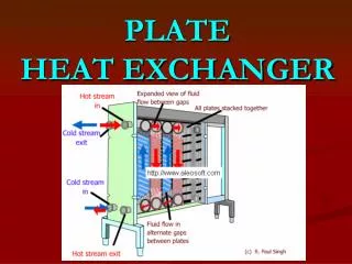
Understanding Heat Exchanger- The very basic
1.53k likes | 2.58k Vues
Understanding Heat Exchanger- The very basic

Understanding Heat Exchanger- The very basic
E N D
Presentation Transcript
My R eading on H eat Exchanger R eading 01- An Introduction for my Aramco AOC’s QM31 Exam Preparations 09th May 2018 Charlie Chong/ Fion Zhang
闭门练功 Charlie Chong/ Fion Zhang
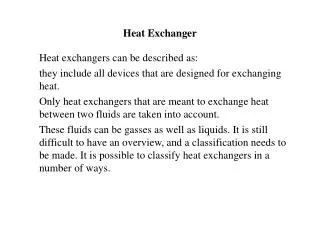
Heat Exchanger Charlie Chong/ Fion Zhang
Heat Exchanger Charlie Chong/ Fion Zhang
Heat Exchanger Charlie Chong/ Fion Zhang
Heat Exchanger Charlie Chong/ Fion Zhang
Charlie Chong/ Fion Zhang Heat Exchanger
Heat Exchanger Charlie Chong/ Fion Zhang
Heat Exchanger Charlie Chong/ Fion Zhang
Heat Exchanger Charlie Chong/ Fion Zhang
Heat Exchanger Charlie Chong/ Fion Zhang
Fion Zhang at Xitang 9th May 2018 Charlie Chong/ Fion Zhang
http://greekhouseoffonts.com/ Charlie Chong/ Fion Zhang
The Magical Book of Tank Inspection ICP Charlie Chong/ Fion Zhang
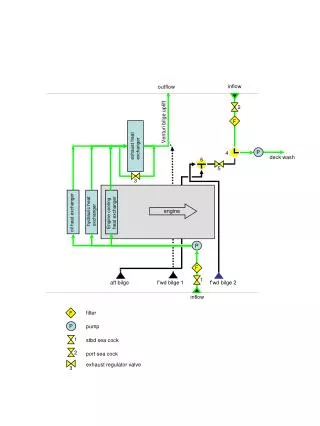
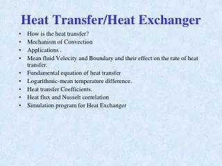
H eat Exchanger https://en.wikipedia.org/wiki/Heat_exchanger A heat exchanger is a device used to transfer heat between a solid object and a fluid, or between two or more fluids. The fluids may be separated by a solid wall to prevent mixing or they may be in direct contact. They are widely used in space heating, refrigeration, air conditioning, power stations, chemical plants, petrochemical plants, petroleum refineries, natural-gas processing, and sewage treatment. The classic example of a heat exchanger is found in an internal combustion engine in which a circulating fluid known as engine coolant flows through radiator coils and air flows past the coils, which cools the coolant and heats the incoming air. Another example is the heat sink, which is a passive heat exchanger that transfers the heat generated by an electronic or a mechanical device to a fluid medium, often air or a liquid coolant. Keywords: transfer heat between a solid object and a fluid (fluids). Charlie Chong/ Fion Zhang
Flow arrangement There are three primary classifications of heat exchangers according to their flow arrangement: In parallel-flow heat exchangers, the two fluids enter the exchanger at the same end, and travel in parallel to one another to the other side. In counter-flow heat exchangers the fluids enter the exchanger from opposite ends The counter current design is the most efficient in that it opposite ends. The counter current design is the most efficient, in that it can transfer the most heat from the heat (transfer) medium per unit mass due to the fact that the average temperature difference along any unit l th i hi h S t t length is higher. See countercurrent exchange. h In a cross-flow heat exchanger, the fluids travel roughly perpendicular to g , one another through the exchanger. g y p p Others Others Charlie Chong/ Fion Zhang
Countercurrent (A) and parallel (B) flows Charlie Chong/ Fion Zhang
Cross Flow Heat Exchanger Charlie Chong/ Fion Zhang
Counter, Parallel and Cross Flow Heat Exchanger Charlie Chong/ Fion Zhang
Countercurrent one pass tube side Charlie Chong/ Fion Zhang
Countercurrent and parallel Two Pass Tube Side Charlie Chong/ Fion Zhang
Countercurrent and parallel 2 Pass Tube Side Charlie Chong/ Fion Zhang
Countercurrent and parallel 2 Pass Tube Side Parallel flow Counter flow Charlie Chong/ Fion Zhang
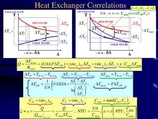
For efficiency, heat exchangers are designed to maximize the surface area of the wall between the two fluids, while minimizing resistance to fluid flow through the exchanger. The exchanger's performance can also be affected by the addition of fins or corrugations in one or both directions, which increase surface area and may: channel fluid flow or induce turbulence. The driving temperature across the heat transfer surface varies with position, but an appropriate mean temperature can be defined. In most simple systems this is the "log mean temperature difference" (LMTD). Sometimes direct knowledge of the LMTD is not available and the NTU method is used. Charlie Chong/ Fion Zhang
LMTD: The logarithmic mean temperature difference (also known as log mean temperature difference or simply by its initialism LMTD) is used to determine the temperature driving force for heat transfer in flow systems, most notably in heat exchangers. The LMTD is a logarithmic average of the temperature difference between the hot and cold feeds at each end of the double pipe exchanger. The larger the LMTD, the more heat is transferred. The use of the LMTD arises straightforwardly from the analysis of a heat exchanger with constant flow rate and fluid. NTU: The Number of Transfer Units (NTU) Method is used to calculate the rate of heat transfer in heat exchangers when there is insufficient information to calculate the Log-Mean Temperature Difference (LMTD). In heat exchanger analysis, if the fluid inlet and outlet temperatures are specified or can be determined by simple energy balance, the LMTD method can be used; but when these temperatures are not available The NTU or The effectiveness method is used. Charlie Chong/ Fion Zhang
Is that only air cooled heat exchanger finned? Charlie Chong/ Fion Zhang
Is that only air cooled heat exchanger finned? Charlie Chong/ Fion Zhang
Is that only air cooled heat exchanger finned? Charlie Chong/ Fion Zhang
Is that only air cooled heat exchanger finned? Charlie Chong/ Fion Zhang
Types ■ Double pipe heat exchangers are the simplest exchangers used in industries. On one hand, these heat exchangers are cheap for both design and maintenance making them a good exchangers are cheap for both design and maintenance, making them a good choice for small industries. On the other hand, their low efficiency coupled with the high space occupied in large scales, has led modern industries to use more efficient heat exchangers like shell and tube or plate. However, since double pipe heat exchangers are simple, they are used to teach heat exchanger design basics to students as the fundamental rules for all heat exchanger design basics to students as the fundamental rules for all heat exchangers are the same. Charlie Chong/ Fion Zhang
Double Pipes Heat Exchanger- Simplest Counter flow Charlie Chong/ Fion Zhang
Double Pipes Heat Exchanger- Simplest Charlie Chong/ Fion Zhang
■ Shell and tube heat exchanger Shell and tube heat exchangers consist of series of tubes. One set of these tubes contains the fluid that must be either heated or cooled. The second fluid runs over the tubes that are being heated or cooled so that it can either runs over the tubes that are being heated or cooled so that it can either provide the heat or absorb the heat required. A set of tubes is called the tube bundle and can be made up of several types of tubes: plain, longitudinally finned, etc. Shell and tube heat exchangers are typically used for high- pressure applications (with pressures greater than 30 bar and temperatures greater than 260 °C). This is because the shell and tube heat exchangers are greater than 260 C). This is because the shell and tube heat exchangers are robust due to their shape. S Several thermal design features must be considered when designing the tubes in the shell and tube heat exchangers: There can be many variations on the shell and tube design. Typically, the ends of each tube are connected to g yp y, plenums (sometimes called water boxes) through holes in tubesheets. The tubes may be straight or bent in the shape of a U, called U-tubes. l th l d i f t t b id d h d i i th Charlie Chong/ Fion Zhang
Counter flow Charlie Chong/ Fion Zhang
Straight Tube Heat Exchanger ( One pass tube side) Shell side nozzle Charlie Chong/ Fion Zhang
Straight Tube Heat Exchanger ( Two pass tube side) Channels Channel Nozzles Channels Pass divider Plenum / Water Box This is straight tube, two pass tube side. Other configuration include U-tube two pass tube side Channel Cover Charlie Chong/ Fion Zhang
U-Tube Heat Exchanger ( Two pass tube side) Plenum (water-box) or Channel? The U- tube bundle (plain) Charlie Chong/ Fion Zhang
Plenums/ Channel Plenum (water-box) or Channel? Charlie Chong/ Fion Zhang
Tube thickness: The thickness of the wall of the tubes is usually determined to ensure: 1. There is enough room for corrosion 2. That flow-induced vibration has resistance 3. Axial strength 4. Availability of spare parts 5. Hoop strength (to withstand internal tube pressure) 6. Buckling strength note1 (to withstand overpressure in the shell) Tube length: heat exchangers are usually cheaper when they have a smaller shell diameter and a long tube length. Thus, typically there is an aim to make the heat exchanger as long as physically possible whilst not exceeding production capabilities. However, there are many limitations for this, including space available at the installation site and the need to ensure tubes are available in lengths that are twice the required length (so they can be withdrawn and replaced). Also, long, thin tubes are difficult to take out and replace. Note 1: In science, buckling is a mathematical instability that leads to a failure mode. When a structure is subjected to compressive stress, buckling may occur. Buckling is characterized by a sudden sideways deflection of a structural member. Charlie Chong/ Fion Zhang
Tube thickness: The thickness of the wall of the tubes is usually determined to ensure: 1. There is enough room for corrosion 2. That flow-induced vibration has resistance 3. Axial strength 4. Availability of spare parts 5. Hoop strength (to withstand internal tube pressure) 6. Buckling strength note1 (to withstand overpressure in the shell) Tube length: heat exchangers are usually cheaper when they have a smaller shell diameter and a long tube length. Thus, typically there is an aim to make the heat exchanger as long as physically possible whilst not exceeding production capabilities. However, there are many limitations for this, including space available at the installation site and the need to ensure tubes are available in lengths that are twice the required length (so they can be withdrawn and replaced). Also, long, thin tubes are difficult to take out and replace. Other considerations include the shorter length tube increase the diameter of the tube bundle and the shell, consequently the shell material thickness is increase. Note 1: In science, buckling is a mathematical instability that leads to a failure mode. When a structure is subjected to compressive stress, buckling may occur. Buckling is characterized by a sudden sideways deflection of a structural member. Charlie Chong/ Fion Zhang
Pressure Vessel- Heat exchanger Charlie Chong/ Fion Zhang
Tube pitch: when designing the tubes, it is practical to ensure that the tube pitch (i.e., the centre-centre distance of adjoining tubes) is not less than 1.25 times the tubes' outside diameter. A larger tube pitch leads to a larger overall shell diameter, which leads to a more expensive heat exchanger. Tube corrugation: this type of tubes, mainly used for the inner tubes (?) , increases the turbulence of the fluids and the effect is very important in the heat transfer giving a better performance. 1.25 x dmin Charlie Chong/ Fion Zhang
Tube Corrugation - Increases the turbulence of the fluids and the effect is very important in the heat transfer giving a better performance. Charlie Chong/ Fion Zhang
Tube Layout: refers to how tubes are positioned within the shell. There are four main types of tube layout, which are: ■ triangular (30°), ■ rotated triangular (60°), ■ square (90°) and ■ rotated square (45°). The triangular patterns are employed to give greater heat transfer as they force the fluid to flow in a more turbulent fashion around the piping. Square patterns are employed where high fouling is experienced and cleaning is more regular. Charlie Chong/ Fion Zhang
Baffle Design: baffles are used in shell and tube heat exchangers to: #1 Direct fluid across the tube bundle. # 2 They run perpendicularly to the shell and hold the bundle, # 3 Preventing the tubes from sagging over a long length. # 4 They can also prevent the tubes from vibrating. The most common type of baffle is the segmental baffle. The semicircular segmental baffles are oriented at 180 degrees to the adjacent baffles forcing the fluid to flow upward and downwards between the tube bundle. Baffle spacing is of large thermodynamic concern when designing shell and tube heat exchangers. Baffles must be spaced with consideration for the conversion of pressure drop and heat transfer. For thermo economic optimization it is suggested that the baffles be spaced no closer than 20% of the shell’s inner diameter. Having baffles spaced too closely causes a greater pressure drop because of flow redirection. Charlie Chong/ Fion Zhang
Consequently, having the baffles spaced too far apart means that there may be cooler (or hot?) spots in the corners between baffles. It is also important to ensure the baffles are spaced close enough that the tubes do not sag. The other main type of baffle is the disc and doughnut baffle, which consists of two concentric baffles. An outer, wider baffle looks like a doughnut, whilst the inner baffle is shaped like a disk. This type of baffle forces the fluid to pass around each side of the disk then through the doughnut baffle generating a different type of fluid flow. Fixed tube liquid-cooled heat exchangers especially suitable for marine and harsh applications can be assembled with brass shells, copper tubes, brass baffles, and forged brass integral end hubs. Charlie Chong/ Fion Zhang
Segmented, Disk & Doughnut and Orifice Baffles. Charlie Chong/ Fion Zhang
Heat Exchanger Baffles #1 Direct fluid across the tube bundle. # 2 They run perpendicularly to the shell and hold the bundle, # 3 Preventing the tubes from sagging over a long length. # 4 They can also prevent the tubes from vibrating. #5 Forcing the fluid to flow upward and downwards between the tube bundle, creating turbulent? Charlie Chong/ Fion Zhang
Heat Exchanger Baffles 0.20 x D min For thermo economic optimization it is suggested that the baffles be spaced no closer than 20% of the shell’s inner diameter. Having baffles spaced too closely causes a greater pressure drop because of flow redirection. Charlie Chong/ Fion Zhang