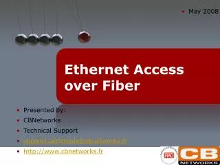
Ethernet Access over Fiber
Ethernet Access over Fiber. Variety of Ethernet Access Solutions – Implementation Scenario. Ethernet over SDH/SONET. Branch. Ethernet over PDH. Branch. RICi-622GE. RICi-622GE. RICi-E1. STM-4/OC-12. GbE. 10BT. GbE. GFP.

Ethernet Access over Fiber
E N D
Presentation Transcript
Variety of Ethernet Access Solutions – Implementation Scenario Ethernet over SDH/SONET Branch Ethernet over PDH Branch RICi-622GE RICi-622GE RICi-E1 STM-4/OC-12 GbE 10BT GbE GFP • Extending the reach of the provider’s network over a variety of access technologies • Consistent Ethernet service across different access technologies Branch Branch RICi-155GE RICi-155GE RICi-4/8E1 MLPPP GbE STM-1/OC-3 GbE 10BT EoPDH ADM Branch RICi-16 Branch Ethernet over DSL 100BT SDH IPDSLAM GFP-VCAT LA-210 F.ETH STM-1/OC-3 EFM Bonding GbE GbE Branch IPDSLAM GbE Service Provider Packet Switched Network LA-110 Egate F.ETH Ethernet over Fiber ATM ASMi-54 ASMi-54 ETX-202 F.ETH GbE SHDSL.bis Headquarters ETX-202A GbE Metro Ethernet GbE GbE Branch
Agenda • Introduction • Product Line Overview • Services and Applications • Service Delivery Tools • Ethernet OAM and SLA • Summary
ETX Application and Product Definition Customer Premises ETX CPE • Clear demarcation between provider’s and Customer’s networks – quickly determine who is responsible for problems affecting service • Operations Administration & Maintenance (OAM)Allow for end-to-end fault management and performance monitoring • Traffic management starting at customer premises • Service Level Agreement MonitoringCustomers demand proof of SLA contract EVC A Customer Premises CPE ETX-A Operator B Operator A Customer Premises ETX CPE EVC B End-to-end OAM between demarcation points
ETX-A NTU – Product Overview New! • Physical Description • Half 19” 1U • AC/DC Power Supply • 2-4 user interfaces • 2 network interfaces • Electrical • 10/100BaseT • 10/100/1000BaseT • All fiber interfaces – SFP based • MEF 9 & 14 Certified for EVPL/EVPLAN • Temperature Hardened with dual power supply option Gigabit Ethernet Fast Ethernet ETX-201A CPE Ethernet 1 or 2 4 Available for Beta! Gigabit Ethernet Gigabit Ethernet ETX-202A CPE Ethernet 1 or 2 4
4 Mbps VoIP 16 Mbps Premium data VoIP 4 Mbps Best Effort data 16 Mbps Premium data Best Effort data Supported Service Topologies: NTU view Port based service: Different user ports POP Customer Premises Edge Device ETX-550/or 3rd Party ETX- series PSN ETH/IP/MPLS GE Ethernet Aggregator E-NTU Flow based service : ‘Service multiplexing‘ Same user port Different flows (e.g VLAN) POP Customer Premises Edge Device ETX-550/or 3rd Party ETX-A series PSN ETH/IP/MPLS GE Ethernet Aggregator E-NTU
MEF Services Terminology: E-LINE CE Ethernet Private Line (EPL) • Replaces a TDM Private line • Dedicated UNIs for Point-to-Point connections • Single Ethernet Virtual Connection (EVC) per UNI Ethernet Virtual Private Line (EVPL) • Replaces Frame Relay or ATM services • Supports multiple EVCs per UNI • Allows single physical connection (UNI) to customer premise equipment for multiple virtual connections UNI UNI Carrier Ethernet Network ISP POP Internet CE UNI UNI Point-to-Point EVC CE Service Multiplexed Ethernet UNI CE UNI Carrier Ethernet Network UNI CE UNI CE Multipoint-to-Multipoint EVC
MEF Services Terminology: E-LAN CE Ethernet Private Line (EPLAN) • Providing LAN over the WAN • Multipoint-to-Multipoint service • Single Ethernet Virtual Connection (EVC) per UNI Ethernet Virtual Private Line (EVPLAN) • Providing LAN over the WAN • Multipoint-to-Multipoint service • Supports multiple EVCs per UNI • Allows single physical connection (UNI) to customer premise equipment for multiple virtual connections UNI UNI ISP POP Internet CE UNI UNI CE Service Multiplexed Ethernet UNI CE UNI UNI CE UNI CE
Supported Service Topologies:Summary • EPL and EPLAN are supported by current ETX products • EVPL and EVPLAN are supported with new ETX A series
Flow Based Forwarding Model Fixed Mapping( cos Queues Strict / wfq Classification according to flow key: 1. CE-VLAN ID 2. CE-802.1p 3. DSCP/ TOS 4. Port CoS per Flow Flow 1 = CoS 3 Flow 1 (EVC 1) CE-VLAN ID Policer per COS CoS 3 = BW profile 1 0 0 (low) 1 1 St / wfq Marking SP-VlanP.bit per CoS: CoS 3= Profile 1= P.bit X Cos 5= Profile 2= P.bit Y 2 2 St / wfq 3 3 St / wfq CoS per Flow Flow 2 = CoS 5 Flow 2 (EVC 2) CE-802.1p Policer per COS CoS 5 = BW profile 2 4 4 St / wfq Flow 2 5 5 St / wfq 6 6 St / wfq 7 7 (max) St / wfq Step 1- Flow Classification Step 2- Flow Mapping: Defines VLAN members per flow Step 3- Assigning Fixed CoS per Flow (other method is CoS per P.bit/DSCP/IP TOS according to user configured profiles) Step 4- Policer Per Cos: Define the CIR/EIR/CBS/EBS Bw criteria per CoS Step 5- Configuring Strict or WFQ priority, according to user configured profiles. Note Priority Queues are fixed to CoS. Step 6- P. Bit priority marking: Adding the P.bit to the SP-Vlan, according to user configured profiles.
Mapping User Traffic to flow • On user ingress traffic is mapped to a flow by one of the following criteria: • VLAN ID • P.Bit • DSCP/TOS • Subscriber port Classification according to flow key: CE-VLAN ID CE-802.1p DSCP/TOS Classification according to flow key: CE-VLAN ID CE-802.1p DSCP/TOS Flow 3 Flow 4 Up to 30 Flows Flow 2 Up to 30 Flows Flow 3 Network Network User User Flow 2 (EVC 2) CE-802.1P= 1, 4, 7 Flow 1 (EVC 1) CE-VLAN: 1, 3,100-120 Mapping Service according to VLAN ID Mapping Service according to P.Bit
Flow Based Forwarding Model Fixed Mapping( cos Queues Strict / wfq Classification according to flow key: 1. CE-VLAN ID 2. CE-802.1p 3. DSCP/ TOS 4. Port CoS per Flow Flow 1 = CoS 3 Flow 1 (EVC 1) CE-VLAN ID Policer per COS CoS 3 = BW profile 1 0 0 (low) 1 1 St / wfq Marking SP-Vlan P.bit per CoS: CoS 3= Profile 1= P.bit X Cos 5= Profile 2= P.bit Y 2 2 St / wfq 3 3 St / wfq CoS per Pbit Pbit1=Cos 1 Pbit7=Cos 7 Flow 2 (EVC 2) CE-802.1p Policer per COS CoS 5 = BW profile 2 4 4 St / wfq Flow 2 5 5 St / wfq 6 6 St / wfq 7 7 (max) St / wfq Step 1- Flow Classification Step 2- Flow Mapping: Defines VLAN members per flow Step 3- Assigning Fixed CoS per Flow (other method is CoS per P.bit/DSCP/IP TOS according to user configured profiles Step 4- Policer Per Cos: Define the CIR/EIR/CBS/EBS Bw criteria per CoS Step 5- Configuring Strict or WFQ priority, according to user configured profiles. Note Priority Queues are fixed to CoS. Step 6- P. Bit priority marking: Adding the P.bit to the SP-Vlan, according to user configured profiles.
Class of Service Mapping • COS can be determined according to: • Flow (EVC) • CVLAN Pbit • Customer DSCP/TOS • Subscriber port EVC1 CoS 1 EVC2 CoS 4 UNI EVC2 Up to 30 Flows Flow 4 Flow 3 CoS 7 EVC3 Flow 2 (EVC 2) CE-802.1P= 1, 4, 7 Network User
Flow Based Forwarding Model Fixed Mapping( cos Queues Strict / wfq Classification according to flow key: 1. CE-VLAN ID 2. CE-802.1p 3. DSCP/ TOS 4. Port CoS per Flow Flow 1 = CoS 3 Flow 1 (EVC 1) CE-VLAN ID Policer per COS CoS 3 = BW profile 1 0 0 (low) 1 1 St / wfq Marking SP-Vlan P.bit per CoS: CoS 3= Profile 1= P.bit X Cos 5= Profile 2= P.bit Y 2 2 St / wfq 3 3 St / wfq CoS per Pbit Flow 2 = CoS 5 Flow 2 (EVC 2) CE-802.1p Policer per COS CoS 5 = BW profile 2 4 4 St / wfq Flow 2 5 5 St / wfq 6 6 St / wfq 7 7 (max) St / wfq Step 1- Flow Classification Step 2- Flow Mapping: Defines VLAN members per flow Step 3- Assigning Fixed CoS per Flow (other method is CoS per P.bit/DSCP/IP TOS according to user configured profiles) Step 4- Policer Per Cos: Define the CIR/EIR/CBS/EBS Bw criteria per CoS Step 5- Configuring Strict or WFQ priority, according to user configured profiles. Note Priority Queues are fixed to CoS. Step 6- P. Bit priority marking: Adding the P.bit to the SP-Vlan, according to user configured profiles.
Policer Per Service/Flow Bandwidth Control • Traffic policing per ingress Service • Dual Token Bucket mechanism (CIR+CBS, EIR+EBS) per policer • TrTCM - 2 rate (CIR/EIR), 3 color (Green/Yellow/Red) marking: • Green: 0 to CIR – always ‘respected’ • Red: above EIR – always discarded • Yellow: between CIR to EIR – Will be respected until the queue reaches a predefine threshold, then it will discarded
Bandwidth Profiles • Bandwidth Profile attributes • CIR – Committed Information Rate, 64 kbps granularity • CBS – Committed Burst Size, 2048-32000 bytes, 1 x byte granularity • EIR – Excess Information Rate, 64 kbps granularity • EBS – Excess Burst Size, 2048-32000 bytes, 1 x byte granularity • Typical Services • VoIP: CIR/CBS according to rate sold, EIR/EBS=0 • High Priority Data, CIR/CBS with typically high EIR/EBS (2 x CIR) • Best Effort: CIR/CBS=0, EIR/EBS according to rate sold CoS 1 CoS 4 EVC2 CoS 7 Network User Flow 2 (EVC 2) CE-802.1P= 1, 4, 7
Flow Based Forwarding Model Fixed Mapping( cos Queues Strict / wfq Classification according to flow key: 1. CE-VLAN ID 2. CE-802.1p 3. DSCP/ TOS 4. Port CoS per Flow Flow 1 = CoS 3 Flow 1 (EVC 1) CE-VLAN ID Policer per COS CoS 3 = BW profile 1 0 0 (low) 1 1 St / wfq Marking SP-Vlan P.bit per CoS: CoS 3= Profile 1= P.bit X Cos 5= Profile 2= P.bit Y 2 2 St / wfq 3 3 St / wfq CoS per Pbit Flow 2 = CoS 5 Flow 2 (EVC 2) CE-802.1p Policer per COS CoS 5 = BW profile 2 4 4 St / wfq Flow 2 5 5 St / wfq 6 6 St / wfq 7 7 (max) St / wfq Step 1- Flow Classification Step 2- Flow Mapping: Defines VLAN members per flow Step 3- Assigning Fixed CoS per Flow (other method is CoS per P.bit/DSCP/IP TOS according to user configured profiles) Step 4- Policer Per Cos: Define the CIR/EIR/CBS/EBS Bw criteria per CoS Step 5- Configuring Strict or WFQ priority, according to user configured profiles. Note Priority Queues are fixed to CoS. Step 6- P. Bit priority marking: Adding the P.bit to the SP-Vlan, according to user configured profiles.
Quality of Service • Class of service management: • Traffic can mapped to eight queues for eight classes of service • Strict priority for low delay low jitter applications such as VoIP • WFQ scheduling for Improving fairness for non critical traffic • Combination of WFQ and Strict Priority • Shaping • Smoothes egress traffic from network port • Based on leaky bucket algorithm with CIR parameter • Queuing • Flexible Combination of WFQ and Strict Priority • Per queue WFQ configurable weight from 1 to 32 • Per queue configurable length 64-32,000 bytes, 1xbyte granularity • Congestion treatment • WRED – Congestion avoidance Fixed Mapping( cos Queues Strict / wfq 0 0 (low) 1 1 WFQ 2 2 3 3 4 4 WFQ 5 5 6 6 7 7 (max) Strict
Flow Based Forwarding Model Fixed Mapping( cos Queues Strict / wfq Classification according to flow key: 1. CE-VLAN ID 2. CE-802.1p 3. DSCP/ TOS 4. Port CoS per Flow Flow 1 = CoS 3 Flow 1 (EVC 1) CE-VLAN ID Policer per COS CoS 3 = BW profile 1 0 0 (low) 1 1 St / wfq Marking SP-Vlan P.bit per CoS: CoS 3= Profile 1= P.bit X Cos 5= Profile 2= P.bit Y 2 2 St / wfq 3 3 St / wfq CoS per Pbit Flow 2 = CoS 5 Flow 2 (EVC 2) CE-802.1p Policer per COS CoS 5 = BW profile 2 4 4 St / wfq Flow 2 5 5 St / wfq 6 6 St / wfq 7 7 (max) St / wfq Step 1- Flow Classification Step 2- Flow Mapping: Defines VLAN members per flow Step 3- Assigning Fixed CoS per Flow (other method is CoS per P.bit/DSCP/IP TOS according to user configured profiles) Step 4- Policer Per Cos: Define the CIR/EIR/CBS/EBS Bw criteria per CoS Step 5- Configuring Strict or WFQ priority, according to user configured profiles. Note Priority Queues are fixed to CoS. Step 6- P. Bit priority marking: Adding the P.bit to the SP-Vlan, according to user configured profiles.
Editing and Marking • SP VLAN Editing: Traffic can be tagged, double tagged or untouched per flow • Marking of Pbit on SP VLAN Network User Flow 2 (EVC 2) CE-802.1P= 1, 4, 7
ETX Product Line – Summary Ethernet Private Line Support CIR/CBS bandwidth profile per port Ethernet Virtual Private Line Support CIR/CBS, EIR/EBS bandwidth profile per EVC.COS
Ethernet OAM & SLA
Standards OAM:Operations Admin. & Maintenance Customer Premises Customer Premises A summary of available Ethernet OAM Mechanisms CPE E-NTU E-NTU CPE Operator B Operator A 802.3ah (Access Link ME) 802.1ag/ Y.1731 (UNI-N to UNI-N ME)
The ETX can provision up to 30 EVC with up to 240 bandwidth profiles and 48 SLA instances ETX SLA Support
Summary • Match the optimal Ethernet NTU for the service requirements: ETX for EPL or ETX-A for EVPL • Offer profitable EVC based service and not just port based service • Support for available bandwidth with CIR/CBS EIR/EBS traffic profiles • Supports a complete OAM package with standard 802.3ah, 802.1ag and Y.1731 • Support for SLA reports to your end-customers
ETX-202A Available Configurations By default unit ships with a wide range 110-240 AC power supply, WRDC is optional Temp. Hardened unit (-30 to 65 Celsius) is available in full 19” with dual DC power supplies
Access Link OAM:Standard IEEE 802.3ah Customer Premises Customer Premises • ETX Support Passive mode designed for network termination • Auto Discovery - Discovers if next hop supports 802.3ah • Loopback - Remote layer 1 loopback of all traffic Excludes 802.3ah OAM messages from loopback • MIB retrieval - No IP needed to get MIB parameters • Remote failure indication • Link Fault upon discovery of disconnect, log alarm, send trap • Dying Gasp: Upon a power failure 802.3ah dying gasp message. Additionally, SNMP trap is sent. CPE ETX ETX CPE Operator B Operator A 802.3ah (Access Link ME)
802.1ag/Y.1731 Service OAM MEP = Maintenance-End-Point MIP = Maintenance-Intermediate-Point • 8 OAM levels • MEP/MIP/MEG concept • Main messages: • CC • LB • LT • AIS • RDI • Lock • (performance measurements) Service OAM MEPs and MIPs Service OAM Header
Continuity Check (CC) OAM Customer Premises Customer Premises • CC OAM Defined per EVC, allows for one-way connectivity monitoring • Loss of Continuity (LOC) is declared (only at the sink side) upon 3.5 seconds without receiving CC OAM frame • Loss of Continuity (LOC) is cleared upon sink receiving 2 CC OAM frames within a window of 3.5 seconds • Upon CC failure • Send trap • Update active alarm log • Update statistics • Optional uplink switch-over CPE E-NTU E-NTU CPE Operator B Operator A CC Sink CC Source CC OAM Frames
Loopback (LB) OAM Customer Premises Customer Premises • Defined per EVC,allows for non-intrusive loopback (round trip) connectivity monitoring • Sent from MEP, looped by either MEP or MIP • LB Failure is declared upon 2 seconds without receiving the specific LB OAM frame • Upon LB failure • Send trap • Update active alarm log • Update statistics • Optional uplink switch-over CPE E-NTU E-NTU CPE Operator B Operator A MEP MEP LB OAM Request LB OAM Reply
Fault Propagation Network port failure Failure propagated to user port • ‘Link down’ status on the Network port causes ‘link down’ status on the user port. • In case of multiple user ports cause ‘link down’ status on all user ports or part of them according to parameter • ‘Wait to restore’ parameter - defines the time between network port becoming ‘up’ and restoring user port link up CPE Switches to alternative path CPE E-NTU Packet Switched Network Eth/IP/MPLS
Diagnostic Loopbacks • Layer 1 Loopback – ETX loopbacks traffic from Rx to Tx • Out of service – disrupts service • Cannot traverse Ethernet bridge • Supported on any ETX port • Performed on all traffic of the ETX port • Loopback activation is via management not OAM protocol • Layer 2 Loopback – ETX loopbacks traffic and swaps MAC Addresses • ETX replaces Source Address with Destination Address • Can traverse Ethernet bridges • Performed per VLAN (or EVC) Tester No Layer L2 Loopback ETX Tester With Layer L2 Loopback
Management • Remote management • In-band management, SNMP based • Dedicated VLAN • Management traffic can be blocked from user port • Management applications • RADview EMS • RADView Lite • Telnet, Web browser • Local management via craft port (RS-232)and/ or Ethernet out of band port. • Optional use of DHCP to automatically obtain IP address and default gateway • Remote software and configuration download • All local configurations can also be done remotely • Full SNMPv3 agent
RADView EMS*- 1/2 • Discover and present of all ETX in the customer network • GUI cut-through application - visual EMS • Provides a visual view of the device with its panel and ports • Provides visual indication of alarm conditions (color coded) • User friendly interface to complex configuration (e.g. OAM) • Statistics presentation • Provides current and historical view of collected statistics from device * RADview-EMS v1.8 available May-08
RADView EMS* – 2/2 • Alarm Management • De-duplication – create a single alarm from multiple alarms • Alarm threshold – create new alarms from alarm conditions • Automatic clearing of alarms – Show only active alarms • Forwarding of alarms to pre-configured 3rd party OSS/NMS • Security management • Create profiles with allowed actions and associated users • Associate permitted actions to each profile • Statistics Collection – TFTP • Efficient collection of device statistics into CSV file format • Easily integrates into customer existing NMS • Northbound CORBA interface * RADview-EMS v1.8 available May-08
Security • Encryption • SSHv2/SSL Secure Telnet and web sessions for management • Secure SNMPv3 communications • Prevent intrusion into management • Access to management station via user ports is blocked (configurable) • Management information from network port only (configurable) • Management VLAN from user ports is blocked • Controlled Access and Authorization • Only specific IP addresses will be allowed to manage the device; • Authorization levels per access method (SNMP, Telnet, Terminal) Read/Write Communities mechanism • RADIUS Centralized Authentication and Authorization of management access • Denial of Service (DoS) Prevention • Rate limitation on traffic direct to CPU • Broadcast/Multicast rate limitation • Ping of Death prevention – no ping larger than 1484 bytes to CPU