Download
1 / 45
470 likes | 600 Vues
Design and Functional Validation of a Mechanism for Dual-Spinning CubeSats. Eric Peters, Kerri Cahoy , Pratik Dave, Joshua Emig , Ryan Kingsbury, Anne Marinan , Andrew Kennedy, Chris Pong, Meghan Quadrino , Devon Sklair , Evan Wise * 16 May 2014

E N D
Design and Functional Validation of a Mechanism for Dual-Spinning CubeSats Eric Peters, Kerri Cahoy, Pratik Dave, Joshua Emig, Ryan Kingsbury, Anne Marinan, Andrew Kennedy, Chris Pong, Meghan Quadrino, Devon Sklair, Evan Wise * 16 May 2014 This work is sponsored by the Assistant Secretary of Defense for Research & Engineering under Air Force Contact FA8721-05-C-0002. Opinions, interpretations, conclusions, and recommendations are those of the authors and are not necessarily endorsed by the United States Government.
Outline • Overview / Motivation • Scanner Assembly Design • Structural Validation • Design iterations • Vibration testing • Thermal Validation • Reduced Gravity Testing • Test environment • Loading cases • Results 42nd Aerospace Mechanisms Symposium
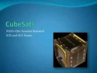
Motivation • Dual-spinning CubeSats • Payload scans Earth cross-track for coverage • Bus fixed in LVLH frame for pointing • MicroMAS: Micro-sized Microwave Atmospheric Satellite • 3U dual-spinning CubeSat for remote weather sensing • 1U passive microwave radiometer payload, MIT Lincoln Laboratory • 2U bus, MIT Space Systems Laboratory • Mechanism needed to join payload and bus structures and facilitate payload rotation • Manifested on Orb-2 ISS resupply mission (June 2014) 42nd Aerospace Mechanisms Symposium
Design Requirements • Scanner assembly must: • Fit in 10cm x 10cm x 3.5cm volume • Rotate 1U, 1kg payload at ~1 Hz (60 rpm) • Have angular position knowledge of 6 arcmin (0.1 deg) or better • Have 8+ electrical feed lines for power/data transfer between bus and payload • Operate continuously in space environment for 1 year Payload Bus MAI-400 ADCS Unit Scanner Assembly Avionics Stack 42nd Aerospace Mechanisms Symposium
COTS Hardware Bearing • NHBB RI-3026 thin section bearing with vacuum-rated cage and lubricant Encoder • MicroEM1500V sensor head rated for high-vacuum • Glass rotary grating disc with 7200 counts per revolution (0.05 degrees per count) Rotor/Stator • AeroflexZ-0250-050-3-104 zero-cogging brushless DC motor Slipring • Aeroflex CAY-1398 with 12 lines for power/data transfer Scanner Assembly Housing 42nd Aerospace Mechanisms Symposium
Design Overview Shaft Bearing Retainer Plate Bearing Cup Bearing Chassis Cover Plate Stator Housing Rotor Base Plate Slipring Encoder Disc Blue: Rotary Green: Stationary Bold: Custom Encoder Sensor Slipring Retainer Encoder Disc Mounting Hub 42nd Aerospace Mechanisms Symposium
Structural Validationof Scanner Assembly 42nd Aerospace Mechanisms Symposium
Scanner Assembly Prototypes 42nd Aerospace Mechanisms Symposium
Scanner Assembly Models 42nd Aerospace Mechanisms Symposium
Rotor/Shaft Interface • Concern: Loss of contact between rotor (stainless steel) and shaft (aluminum) due to differential thermal expansion at low temperatures • Tested several mating methods 42nd Aerospace Mechanisms Symposium
Vibration Testing Engineering Design Unit Flight Unit March 2014 Spectrum provided by launch integrator Flight acceptance test, “soft-stow” configuration Max accelerations experienced: 0.5 GRMS (X-direction) 2.3 GRMS (Y-direction) 1.0 GRMS (Z-direction) • March 2013 • GEVS qualification input spectrum • Goals of test: • Verify bearing could survive vibe environment and still function • Verify glass encoder disk would not shatter during vibe • Verify epoxy bond between encoder disk and hub would survive • Unit survived test with no noticeable damage 42nd Aerospace Mechanisms Symposium
Thermal Validationof Scanner Assembly 42nd Aerospace Mechanisms Symposium
Thermal Testing Engineering Design Unit Flight Unit March 2014 Temperature range Min: -17C Max: 60C Total duration: 100 hours Goals: Verify full system performance across expected operational temperature range Verify system survives worst-case expected hot and cold temperatures • March 2013 • Temperature range • Min: -8.5C • Max: 65C • Total duration: 15 hours • Goals: • Characterize encoder signal voltage performance versus temperature • Characterize encoder signal frequency performance versus temperature • Test effect of thermal expansion on press-fit interface 42nd Aerospace Mechanisms Symposium
Encoder Performance Nominal = 800 mV, minimum acceptable = 400 mV Minimum acceptable voltage is 50% lower than nominal Minimum observed voltage is only 13.75% lower than nominal Encoder V still in nominal range (> 400 mV) despite drop at higher temps 42nd Aerospace Mechanisms Symposium
Encoder Performance (2) Nominal signal frequency = 7200 Hz +0.21% -0.24% Encoder signal frequency stable over temp stable scanner performance 42nd Aerospace Mechanisms Symposium
Thermal Testing Results • Encoder signal frequency and strength exhibited nominal performance across entire expected satellite on-orbit temperature range • Press-fit interface tested to -8C No issues • Flight unit epoxy interface and encoder head tested to -17C and +60C extremes • Encoder functioned nominally below minimum stated operational temperature of 0C • Scanner assembly performance stable across entire temperature range 42nd Aerospace Mechanisms Symposium
Microgravity Testing 42nd Aerospace Mechanisms Symposium
Test Environment • Tested engineering model satellite through NASA microgravity flight opportunity program • April 21-25, 2014 • Over four flights, encountered a total of: • 112 Zero-G parabolas • 32 Lunar parabolas • 16 Martian parabolas • Tests included satellite strapped down to test platform and free-floating 42nd Aerospace Mechanisms Symposium
Strapped-Down Orientations Gravity vector aligned with satellite Y axis Bearing radially loaded Gravity vector aligned with satellite X axis Bearing axially loaded 42nd Aerospace Mechanisms Symposium
Results – Radially Loaded • Lunar parabolas • Bearing radially loaded by gravity vector • Min/max accelerations seen: • 0.16Gduring parabolas • 1.8Gduring pullouts • Rotation rate was steady across 10 changes in gravity level • < 0.75% error during constant rotation • Max error: • 17% during spin-up 42nd Aerospace Mechanisms Symposium
Results – Axially Loaded • Zero-Gparabolas • Bearing axially loaded by gravity vector • Scanner Assembly commanded to accelerate and decelerate during parabolas • Rotation rate unaffected by changing gravity levels • < 0.01% error during constant rotation • Max error 2.5% during spin up/down 42nd Aerospace Mechanisms Symposium
Results – Free Floating • Satellite allowed to free-float during zero-Gparabolas • Held during 2G pullouts; bearing axially loaded • Scanner Assembly commanded to accelerate, hold constant rate • Performance was unaffected by changing accelerations • < 0.3% error during constant rotation • Max error 2.5% during spin-up 42nd Aerospace Mechanisms Symposium
Reduced Gravity Summary • The scanner assembly experienced a total of • 5000 seconds in hyper-gravity (1.8G) • 2000 seconds in microgravity • 900 seconds in Lunar gravity (0.16G) • 650 seconds in Martian gravity (0.38G) • Scanner assembly exhibited constant rotation rate across changing gravity levels when loaded both axially and radially • Demonstrated ability to accelerate and decelerate across changing gravity levels 42nd Aerospace Mechanisms Symposium
Conclusions • Validated scanner assembly: design achieves requirements • Successful iterative design process • Successful component-level test of encoder/scanner performance with temperature at vacuum pressure • Flight unit performed nominally after vibration and during/after thermal-vacuum testing • Parabolic flight campaign proved design functionality in Lunar, Martian, micro-, and hyper-gravity environments • Scheduled for launch on June 10, 2014 Completed MicroMAS flight unit 42nd Aerospace Mechanisms Symposium
Backup Slides 42nd Aerospace Mechanisms Symposium
Rotor/Shaft Mating Tests • Purpose: Test strength of rotor/shaft interface • Use peak torque provided by motor (4 in-lb) on epoxy and tolerance ring • Setup:Used identical flight-like shaft + rotor ring sets 1.546 in 0.005 in 0.550 in • Shaft • Aluminum alloy 6061-T6 • Cut grooves for epoxy • Found deeper groove needed for tolerance ring • Ring • A513 mild steel • Smooth internal surface 0.390 in Shaft + rotor ring test rig 42nd Aerospace Mechanisms Symposium
Torque Testing Setup Grade 8, 1/2-13 bolt Lock washer • 1/2”-13 bolt secured through bore in center of test shaft • Flat washers placed between shaft-nut and shaft-bolt • Fastener installation torqued to 120 in-lb • Ring held by vise while torque applied to the bolt Nut Lock washer 42nd Aerospace Mechanisms Symposium
Tolerance Ring Attempts • First attempt, tolerance ring forced out of the groove • Initial 0.005" groove depth too shallow • Machined new shaft with groove depth of 0.022” • Designed to fully retain the 0.020” un-corrugated portion and ¼ of the corrugated portion • Trimmed length of ring to maintain gap of 0.060” between edges • Gap of 0.040” - 0.080” recommended by product engineers Image from:USA Tolerance Rings 42nd Aerospace Mechanisms Symposium
Torque Testing Results • First, test to peak torque provided by motor during nominal operations (4 in-lb) • If successful, then test to point of failure • Results: • Both epoxy and tolerance rings survived up to 65 in-lbtorque • Point of failure was not reached for either epoxy or tolerance ring • At 65 in-lb, washers slipped at interface with shaft • Test was halted and not continued to higher torques • Note: • Tolerance ring: tested to less than max torque capacity of rings(65 in-lb test << 675 in-lb predicted capacity) • Epoxy: tested to much less than epoxy shear strength at ~25°C (tested 44 psi << rated 3800 psi) 42nd Aerospace Mechanisms Symposium
Vibration Testing Spectra 14.1 GRMS overall 9.47 GRMS overall 42nd Aerospace Mechanisms Symposium
“Soft Stow” Configuration 42nd Aerospace Mechanisms Symposium
EDU Thermal Testing • Purpose: Characterize encoder + motor assembly performance over operational/survival temperatures in vacuum • Analog output from encoder Oscilloscope • Digital output from encoder to motor controller PC • Temperature data w/ 9 x 100Ω RTDs Agilent DAQ 42nd Aerospace Mechanisms Symposium
EDU Thermal Test Profiles Encoder specified operational temperature range = [0,70] °C Predicted on-orbit temperature range = [-5,25] °C 42nd Aerospace Mechanisms Symposium
EDU TVac Profile Motor commanded to continuously spin at 60 rpm during entirety of both tests Test 1: Cold Test Test articles cooled to -8.5 °C, then returned to ambient Test 2: Thermal Cycling Test articles cooled to 0 °C, then heated to 65 °C 70 60 50 40 Temperature (°C) 30 20 10 0 0 2 4 6 8 10 12 14 16 18 0 5 10 15 20 25 -10 Time since pump-down (1000 seconds) Time since pump-down (1000 seconds) Motor and encoder operated nominally throughout all tested temperature ranges 42nd Aerospace Mechanisms Symposium
Flight TVac Profile Reaction Wheels Motherboard RW Interface PCB 42nd Aerospace Mechanisms Symposium
Encoder Signal at -5 °C Signal is filtered and averaged by oscilloscope, as will be similarly done by on-board avionics Nominal signal amplitude: > 400 mV Nominal signal frequency: 7.200 kHz Active computation of signal frequency Active computation of signal amplitude (voltage) Encoder signal amplitude and frequency are both well within nominal range 42nd Aerospace Mechanisms Symposium
Encoder Signal at +60 °C Signal is filtered and averaged by oscilloscope, as will be similarly done by on-board avionics Nominal signal amplitude: > 400 mV Nominal signal frequency: 7.200 kHz Active computation of signal frequency Active computation of signal amplitude (voltage) Though the encoder signal amplitude decreased at higher temperature, the signal amplitude and frequency are both still within nominal range 42nd Aerospace Mechanisms Symposium
Error – Radially Loaded 42nd Aerospace Mechanisms Symposium
Error – Axially Loaded 42nd Aerospace Mechanisms Symposium
Error – Free Float 42nd Aerospace Mechanisms Symposium
Flight 2, Zero-G • < 0.015% error during constant rotation • Max error: 8% during spin-up/spin-down 42nd Aerospace Mechanisms Symposium
Flight 2, Lunar/Martian • Steady behavior during spin-up and constant rotation periods • Phase shift likely caused by human error during data processing 42nd Aerospace Mechanisms Symposium
Flight 3, Lunar/Martian • < 0.015% error during constant rotation • Max error < 2.5% during spin-down 42nd Aerospace Mechanisms Symposium
Flight 4, Free-float • < 0.1% error during constant rotation • Max error< 2.5% during spin-up 42nd Aerospace Mechanisms Symposium
Flight 4, Lunar/Martian • < 0.02% error during constant rotation 42nd Aerospace Mechanisms Symposium