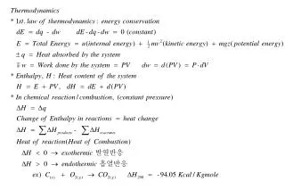
Enhanced Sectorisation for PSB H0-H Injection: Safety and Efficiency Analysis
This analysis explores the potential advantages of re-sectorising the PSB H0-H injection sector. The proposed changes could significantly reduce radiation exposure during pumping and leak detection, create additional installation space for stripping foils, and relocate sector valves away from radioactive areas. The discussion includes various case studies to compare different configurations and their effects on pressure profiles and intervention times. Ultimately, the findings suggest improved safety and operational efficiency for the system.

Enhanced Sectorisation for PSB H0-H Injection: Safety and Efficiency Analysis
E N D
Presentation Transcript
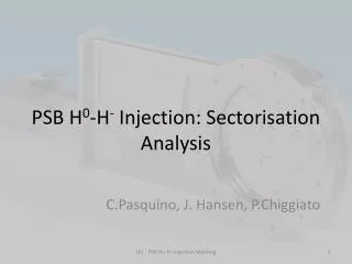
PSB H0-H- Injection: Sectorisation Analysis C.Pasquino, J. Hansen, P.Chiggiato LIU - PSB Ho-H- Injection Meeting
Why re-sectorising this sector? At the moment the sector valves are foreseen to be positioned right before and right after the stripping foils; Foil • A different sectorisation would allow: • Less radiation for TE/VSC during pumping and leak detection. • More space for installation of stripping foils. • Positioning of the sector valves away from a radioactive area; • Less problems to find space for pumping and venting. • A bigger sector might help in controlling the initial phase of the pump down and venting, preventing a sudden rupture of the graphite foils (experimental test are ongoing…) Dump LIU - PSB Ho-H- Injection Meeting
Several Case Study (1) Option1 Reference case study, always for 1 ring. Sector valve at the third manifold to the left of the injection zone and after the stripping foil. Sector valve at the third manifold to the left of the injection and at the third to the right. = Sector Valve Option2 Option3 LIU - PSB Ho-H- Injection Meeting
Several Case Study (2) Sector valve at the first manifold to the left of the injection and after the dump. With double SIPs between BSW 1&2. Sector valve at the first manifold to the left and at the first manifold on the right, With double SIPs between 1&2 and 3&4. Option 4 Option 5 The pump down curve for all the options has been studied: for case 1 , 4 and 5, the pressure profile along the beam pipe will be presented as well. LIU - PSB Ho-H- Injection Meeting
Pump down studies: option 1 The pump down of a sector is divided in two stages: A fix TMP group takes care of the pump down from atmospheric pressure down to 1*10-6 mbar; At 1*10-6 mbar the sputter ion pump are flashed and switched on. The time from atmospheric pressure to 1*10-3 mbar is not included and it will depend on the experimental results from the stripping foils test (ongoing). If we consider that at 1*10-7 mbar a first low intensity beam can be sent 5 to 6 hours after the end of the intervention including the leak detections. TMP ON SIP ON TMP & SIP Connections LIU - PSB Ho-H- Injection Meeting
Pump down studies: option 2 The intervention time is about 2 hours more than option 1. SIP SIP SIP Option 2 LIU - PSB Ho-H- Injection Meeting TMP gate
Pump down studies: option 3 The intervention time is the same as option 2. SIP SIP SIP SIP SIP Option 3 TMP gate LIU - PSB Ho-H- Injection Meeting
Pump down studies: option 4 The intervention time is the same as option 2. 2X SIP Option 4 LIU - PSB Ho-H- Injection Meeting TMP gate
Pump down studies: option 5 The intervention time is about 30 minutes more than option 1. 2X SIP 2X SIP Option 5 TMP gate LIU - PSB Ho-H- Injection Meeting
Pressure Profile studies : Option 1 The pressure profiles have been studied for these options after pump down with sector valves open. Read Pressure Point SIP SIP SIP SIP SIP SIP SIP LIU - PSB Ho-H- Injection Meeting 0 Position (m)
Pressure Profile studies : Option 4 The pressure profiles have been studied for these options after pump down with sector valves open, considering the displacement of 1 of the SIP upstream. Read Pressure Point SIP 2XSIP SIP SIP SIP SIP SIP LIU - PSB Ho-H- Injection Meeting 0 Position (m)
Pressure Profile studies : Option 5 The sputter ion pumps must be displaced where the sector valves are: there is space to install a further pump upstream, but no space for replacing the downstream one. Read Pressure Point SIP SIP SIP SIP SIP SIP SIP LIU - PSB Ho-H- Injection Meeting 0 Position (m)
Pressure Profile studies : Option 1, 4 and 5, comparisons No sublimators taken into account!! Read Pressure Point LIU - PSB Ho-H- Injection Meeting 0 Position (m)
Intervention probability • Option 1: high risk for the foil integrity and foil mechanical assembly, high risk for MTV mechanical assembly (high intervention dose). • Option 3 and 5: same as option 1, more stainless steel surface and dumps and we lose the dump conditioning every time the system is vented to air equal longer time to achieve nominal beam. (less personal dose for pumping and leak detection). • Option 2 and 4: same as for option 1. More stainless steel surface, but not critical. More space in injector zone (less personal dose for pumping and leak detection) and no loss of the dump conditioning. LIU - PSB Ho-H- Injection Meeting
Conclusions • The displacement of these sector valves would allow for a safer intervention scenarios. • It would create a bigger vacuum sectors, which might improve the initial phase of the venting and pumping of the stripping foil mechanism. • Option 5 allows for doubling the SIP connected on both sides of the stripping foil mechanism, we can maintain the same level of vacuum in the stripping foil, but higher pressure down stream. The dump region will be vented at each intervention and there is a risk it will take longer before we can inject nominal beam. • Option 4 gives a longer intervention time, but the dump would be protected from venting so shorter time to go to nominal beam and we will accumulate less personal dose. LIU - PSB Ho-H- Injection Meeting
Stripping foil venting – pumpdown testbench Flowmeter (venting phase) Injection (Pumpdown phase) Thanks to Remy et Yves for assembling the foils!! • Injection during pumpdown to slow down the descent in pressure in its initial phase; • Injection at known different fluxes, checking the foil integrity; LIU - PSB Ho-H- Injection Meeting