ROADM Network Elements
ROADM Network Elements. Brandon Collings Optical Networks Research, JDSU brandon.collings@JDSU.com OFC 2007 OThR1. Overview. Market Drivers for ROADM Networks Primary ROADM Network Features ROADM Node Building Blocks and Node Architectures

ROADM Network Elements
E N D
Presentation Transcript
ROADM Network Elements Brandon Collings Optical Networks Research, JDSU brandon.collings@JDSU.com OFC 2007 OThR1
Overview • Market Drivers for ROADM Networks • Primary ROADM Network Features • ROADM Node Building Blocks and Node Architectures • Physical Layer Operational Features and Automation • ROADM Component Characteristics and System Performance • Network Management • Current and Future Trends
Bandwidth is increasing… • Capacity increase is significant • But the real story is how that capacity is evolving… source: G.K. Cambron, AT&T, OFC/NFOEC ‘06
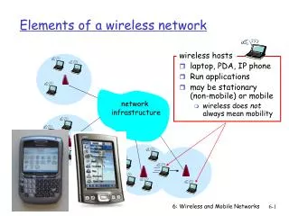
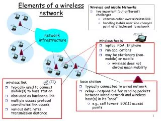
US HQ Tokyo Drivers of the Today’s All Optical Networks Triple Play Services Rich Media Services Business Services
Consumer Driven Applications • Downloading TV programs from the Web is becoming more popular with consumers. There was a 39% increase in subscription rentals of TV content and a 255% increase in TV-title digital video downloads between August 2005 and August 2006. (NPD Group) • In December 2006, Xbox Live surpassed 4 million members worldwide. Microsoft expects it to surpass 6 million members by the summer of 2007. • According to YouTube, it is currently serving 100 million videos per day, with more than 65,000 videos being uploaded daily. • In January of 2007 Apple announced that more than two billion songs, 50 million television episodes and over 1.3 million feature-length films have been purchased and downloaded from the iTunes Store Content and bandwidth is evolving in a peer-to-peer topology Bandwidth is increasing and predictability decreasing
Rich Media Services Have Changed the Network Model The “Telephony Network” The Agile Optical Network • Sonet-SDH network • Bandwidth predictable • Traditional usage voice, dial-up • Low bandwidth, low use and short duration • DWDM Network • High bandwidth applications • Always-on • Unpredictable traffic and growth patterns
Market Overview : Technology Trends Agile + Fixed CAGR = 19% 39% 61% Rapid Transition from Fixed to Agile 79% Agile CAGR = 55% 21% Source: Ovum-RHK, Transition to agile optical network drives ROADM and related modules growth, 2/2006 CAGR data is 2004-2010
The Agile Optical Network is Happening Today “While not everyone has announced their deployment of Agile Optical Networks, most are using them in some form or fashion” Brett Azuma Exec VP, Ovum-RHK
Let’s just get this out of the way… Unsuccessful Business Case COST! Successful Business case in some market segments A Technology and Manufacturing Challenge
Static Networks Based on Fixed-Wavelength Filters • Topology and capacity/node determined at time of network design • Traffic projections based upon best estimates at the time • Frequently changes even during design/bid/deployment • Not always cost effective to “overbuild” the system • Can lead to premature system exhaust • Expected system lifetime: 5-10 yrs • Traffic projections not accurate leading to premature system exhaust • Insufficient l’s available to hot spots • Unlit l’s to cold spots cannot be utilized • Topology is inconsistent for emerging applications • Telephony, SAN, Enterprise, VoD, TBD topologies look different Hub Ch 1-8 Ch 1-32 Ch 9-16 Ch 17-24 Ch 25-32 Physical WDM Ring
(2x1 Switch+VOA) Array DEMUX MUX VOA Tap PD TAPs & PD Arrays ADD CHANNELS DEMUX ROAM TAP & PD Array DROP CHANNELS Demux-T ROADMs Enable Any-Node-to-Any-Node Topologies • Provision wavelengths independently between nodes • No blocking extends system life to capacity limitation • Relieves need for accurate traffic growth forecasting ROADM ROADM ROADM ROADM ROADM Physical WDM Ring
All Optical Ring Interconnect Reduce OEO Costs • Ring-to-Ring traffic previously electrically cross-connected • Required O/E transponders on both rings • Requires electrical switch and grooming fabric • Multi-Degree ROADM Nodes enable inter-ring traffic to remain in the optical domain • Removes cost of OEO and electrical fabric • ROADM Nodes capable of remotely routing full capacity of channels without additional equipment • OEO transition requires additional equipment with each wavelength • Electrical switching fabrics generally not as scalable • Traffic can be routed without craft visit to node • ROADMs are bit-rate independent • Implement higher line rates when, where and if the economics prove in ROADM ROADM ROADM ROADM OEO ROADM ROADM ROADM
All Optical Ring Interconnect Reduce OEO Costs • Ring-to-Ring traffic previously electrically cross-connected • Required O/E transponders on both rings • Requires electrical switch and grooming fabric • Multi-Degree ROADM Nodes enable inter-ring traffic to remain in the optical domain • Removes cost of OEO and electrical fabric • ROADM Nodes capable of remotely routing full capacity of channels without additional equipment • OEO transition requires additional equipment with each wavelength • Electrical switching fabrics generally not as scalable • Traffic can be routed without craft visit to node • ROADMs are bit-rate independent • Implement higher line rates when, where and if the economics prove in ROADM ROADM ROADM ROADM ROADM ROADM ROADM
Accelerated Service Roll-out • Remote provisioning and automated control plane enable more rapid service commissioning • Shorter Time-to-Revenue and Return on Investment • Increased customer capture • Shorter and predictable deployment intervals • Network topology flexibility reduces network configuration churn
Four Basic Types of ROADM Components Tunable Channel Filter Wave Blocker (WB) Tunable Band Filter Wavelength Selectable Switch (WSS) PLC ROADM
Typical Tunable Channel Filter Node Architecture • Independent access to all wavelength channels • Number of Add/Drop ports less than maximum wavelength count • Tx/Rx ports are wavelength provisionable (colorless) • Supports drop and continue • Waveblocker required for wavelength reuse • Add channels power equalized • Express channels equalized if WaveBlocker included • Supports 2-degree nodes To East From West Coupler Coupler OA OA Wave Blocker Tunable Filters Transmitters Receivers Rx Rx Rx Rx Tx Tx Tx Tx DROP ADD
Typical Tunable Band Filter Node Architecture • Channels added/dropped in bands • Width of bands may be fixed or adjustable • Band is tunable in wavelength • Tx/Rx ports are wavelength specific (colored) • Wavelengths may be reused • Add channels power equalized • Does not support drop and continue • Supports 2-degree nodes To East From West OA OA Band Filter Band Filter AWG AWG Transmitters Receivers Rx Rx Rx Rx Tx Tx Tx Tx DROP ADD
Typical WaveBlocker Node Architecture • Independent access to all wavelength channels • Tx/Rx ports are wavelength specific (colored) • Express and Add channels are power equalized • Supports drop and continue • Supports 2-degree nodes To East From West Block Coupler Coupler OA OA Wave Blocker AWG AWG Transmitters Receivers Rx Rx Rx Rx Tx Tx Tx Tx DROP ADD
Typical PLC ROADM Node Architecture • Independent access to all wavelength channels • Tx/Rx ports are wavelength specific (colored) • High level of integration • Add direction wavelength multiplexing • Per channel power monitoring (Add and Express) • Add and Express channel power equalization • Express or Add channel selection • Supports 2-degree nodes To East From West Coupler OA OA PLC ROADM AWG Transmitters Receivers Rx Rx Rx Rx Tx Tx Tx Tx DROP ADD
Mux and Demux WSS Node Architecture • Independent access to all wavelength channels • Number of Add/Drop ports less than maximum wavelength count • Cascade secondary WSS components off primary WSS for additional ports • Tx/Rx ports are wavelength provisionable (colorless) • Express, Add and Drop channels power equalized • Does not support drop and continue • Supports 2-degree nodes To East From West OA OA WSS WSS Transmitters Receivers Rx Rx Rx Rx Tx Tx Tx Tx DROP ADD
Demux WSS Node Architecture • Independent access to all wavelength channels • Number of Add/Drop ports less than maximum wavelength count • Cascade secondary WSS component off primary WSS for additional ports • Tx/Rx ports are wavelength provisionable (colorless) • Express, Add and Drop channels power equalized • Does not support drop and continue • Supports 2-degree nodes To East From West Coupler OA OA WSS Coupler Transmitters Receivers Rx Rx Rx Rx Tx Tx Tx Tx DROP ADD
Mux Nx1WSS Demux 1xN WSS North Out North In South Out South In East Out East In West Out West In Multi-Degree WSS Node Architectures • Demux WSS selectively routes wavelengths to destination output degrees • Mux WSS selectively accepts wavelengths intended for its respective degree • Blocks undesired wavelengths • Replace Mux WSS with power combiner • Demux WSS selectively routes wavelengths intended for each respective degree • Provides isolation for those wavelengths not intended for a given degree • Replace Demux WSS with power splitter • Mux WSS selectively accepts wavelengths intended for its respective degree • Provides isolation for those wavelengths not intended for its respective degree
Coupler Coupler Coupler OA OA OA Coupler Coupler Coupler Tx Tx Tx Tx Tx Tx Tx Tx Tx Tx Tx Tx ADD ADD ADD Multi-Degree Demux WSS Node Architecture North OA OA Rx Tx Rx Coupler Tx DROP Coupler ADD Rx WSS Tx East Rx Tx West OA WSS Rx Rx Rx Rx OA WSS DROP Rx Rx Rx Rx Rx Rx DROP WSS Rx Rx DROP South OA
Coupler OA Coupler Tx Tx Tx Tx ADD Characteristics of Multi-Degree Demux WSS Architecture • Supports any wavelength from any degree to any degree • Drop port count limitations due to port sharing with inter-degree connections • Add/drop ports are colorless • No add port filtering rejects rogue wavelengths or noise • Does not support drop and continue • Drop and express channel equalization provided by WSS • Add port VOAs provide add channel equalization Rx Rx DROP WSS Rx Rx South OA
Coupler Coupler Coupler OA OA OA AWG AWG AWG Rx Rx Rx Rx Rx Rx Rx Rx Rx Rx Rx Rx DROP DROP DROP Multi-Degree Mux WSS Node Architecture North OA Tx Tx ADD WSS AWG Tx East Tx West WSS OA AWG Tx Tx Tx Tx WSS OA ADD AWG Tx Rx Tx Tx Tx Tx Tx Rx AWG DROP ADD AWG WSS Tx Rx Coupler Tx Rx ADD South OA OA
Characteristics of Multi-Degree Mux WSS Architecture • Supports any wavelength from any degree to any degree • Add/drop ports present for all supported channels • Add/drop ports are colored • Add port filtering rejects rogue wavelengths • Supports drop and continue • Add and express channel equalization provided by WSS • No per channel power control on drop ports (unless VOAs included) Tx Rx Tx Rx AWG DROP ADD AWG WSS Tx Rx Coupler Tx Rx South OA OA
Coupler Multi-Degree Mux and Demux WSS Node Architecture North OA OA Rx Tx Coupler Rx Tx DROP ADD Rx WSS Tx WSS East Rx Tx West OA WSS OA WSS Tx Tx Tx Tx Coupler OA Rx Rx Rx Rx OA WSS ADD DROP WSS Tx Rx Tx Rx Tx Tx Tx Tx Rx Rx Rx Rx DROP WSS ADD Tx Rx WSS Tx Coupler Rx ADD DROP South OA OA
Characteristics of Multi-Degree Mux and Demux WSS Architecture • Supports any wavelength from any degree to any degree • Drop port count limitations due to port sharing with inter-degree connections • Add/drop ports are colorless • Add port filtering rejects rogue wavelengths and noise • Supports drop and continue • Add and express channel equalization provided by Mux WSS • Demux WSS provides drop channel power control Tx Rx Tx Rx DROP WSS ADD Tx Rx WSS Tx Coupler Rx South OA OA
Optical Layer Architectural Feature Comparison ü Intrinsically Supported O Support depends upon particular configuration or inclusion of specific elements (i.e. VOA’s) - Not Supported
ROADM Network Operational Features and Automation • Reconfigurability requires visibility into the optical layer and automated control • Monitor wavelength routing • Monitor optical layer performance • Provide feedback for channel power adaptation • Automated optical layer eases installation and operational activities • Quicker, cheaper, more predictable installation intervals • Reduces required craft training and in the field measurements • Minimizes complex activities such as power measurement and balancing • Neighbor node and configuration discovery • Minimizes errors • Provides fault correlation • Automated control enables increased performance and reliability • Longer system reach due to channel power equalization • Increased adjustment accuracy than possible manually • Performance monitoring and early warning alarms • Simplifies support for alien wavelengths
Possible Monitored Parameters Optical channel power OSNR Wavelength alignment Wavelength ID or tag Characteristics Measurement refresh rate Single or multi-input (shared) Single channel dynamic range Adjacent channel dynamic range Accuracy Optical Layer Monitoring Components Two Basic Types Parallel Scanning AWG Scanning Tunable Filter
Automatic Optical Power Management • ROADM networks have a rich complement of power control actuators • Per channel power control at ROADMs • Total average gain control at EDFAs
Automated Channel Power Equalization • Channel power levels become unequal • Accumulated optical amplifier gain shape • Non-uniform fiber loss • Inter-channel Raman pumping • Optical elements • Added channels require leveling when introduced into system • Many transponders do not produce tightly controlled output power • Power level may not be appropriate • Insertion loss of add path can vary • Feedback algorithms control both optical amplifier and per channel attenuation • Optical amplifiers operate on all channels • Goal is to minimize amplifier gain • Minimizes OSNR degradation
Long Term Effects • Fiber loss aging • PDL • Laser aging • Spectral Hole Burning • Gain spectrum changes due to change in channel loading • Change can be positive or negative • EDFA Transient • Upstream fiber break or power failure • Rapid decrease in input power and/or channel count • EDFA reacts to maintain stable gain for surviving channels Srivastava et al, OFC 1995 Channel Power Level Transient Timescales min/hour/day/year ~2ms ~100ms time
Reaction Rate of Power Control • Power Measurement (Optical Channel Monitor) • Parallel techniques: capable of sub-millisecond • Scanning techniques: 10’s of ms to seconds • Technology dependent • Multi-Input OCMs • Utilizes high isolation Nx1 selection switch • Decreases refresh rate by >N times • Attenuation Change Actuation • VOAs: typically on the order of milliseconds • ROADMs: several milliseconds to seconds • Technology and magnitude of attenuation change dependent
Power Level Transient Mitigation • Transient suppression in the EDFA • ROADM and VOA reaction rates currently insufficient • Gain change due to SHB requires ROADM attenuation correction • Gain change is typically small per amplifier (<0.5dB) • Change to channel power can accumulate with EDFA cascade • Depending upon ROADM attenuation speeds, some channels may be “unequalized” for several milliseconds • During this period, system performance may be impacted • Duration is sufficient to trigger protection switch if impact is sufficiently severe • System design concern on extent to which system reach can be extended by capitalizing on channel power equalization
Commissioning/Decommisioning • Intentionally slow introduction and removal of optical power during network activities • Channel installation or removal • EDFA installation or removal • Fiber connection or disconnection • Power control algorithms can react and keep system in equilibrium
Cascading ROADM Nodes • Details of the channel filtering become significant as number in cascade increases • Amplitude Response • Wide, flat top shape required • Phase response • a.k.a group delay which causes dispersion • Group delay ripple and structure must be minimized • PMD • Channel spacing and Bit Rate • 10Gb/s typically not significantly impacted • 40Gb/s over 50GHz ROADMs has been deployed • Using advanced modulation techniques
Typical WSS-based Node and Port Isolation …what happens to li in WSS? port isolation (PIso) from deg 1 li,port_1 port selected to pass splitter Degree 1 from deg 2 li,port_2 AWG from deg 3 li,port_3 from deg 4 li,port_4 splitter Degree 2 Output (at li) is coherent combination of li,port_2 along with m-1 li signals, each suppressed by PIso AWG from deg m-1 li,port_m-1 from add li,add 1xm WSS splitter Degree m-1 AWG AWG
OSNR Penalty versus Port Isolation • Assumes nominal attenuation of 4 dB for channel power equalization • N is the number of interfering signals present
Network Management • Physical Layer Configuration Discovery • Inventory • Adjacent nodes • Intra-node element interconnection verification • Wavelength Routing Verification • Performance Monitoring • Full visibility into active wavelength performance • Threshold crossing warnings and alarms • Alarm Correlation • Prioritize alarm closest to root cause • Suppress other alarms resulting from fault condition
Current and Future General Trends • Increased Component Integration • Reduce cost through circuit pack consolidation • Increased Use of Open Photonic Layers • Improving physical layer automation increases acceptance criteria for non-native (alien) wavelengths • IP migration and proliferation of pluggable DWDM interfaces • ROADMs Penetrating Edge/Access • Highly cost sensitive • Perhaps most rapidly evolving network space • Enhanced In-situ Diagnostics • Link performance and engineering rules validation • Fiber plant characterization (dispersion, PMD, etc.) • Increased utilization of topology flexibility and wavelength tunability • Restoration and disaster recovery • Load balancing • Protection switching Thank You