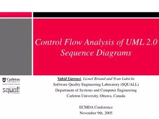
Static Control-Flow Analysis for Reverse Engineering of UML Sequence Diagrams
200 likes | 505 Vues
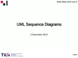
Static Control-Flow Analysis for Reverse Engineering of UML Sequence Diagrams. Atanas (Nasko) Rountev Ohio State University with Olga Volgin and Miriam Reddoch. Example of a UML Sequence Diagram. start:X. p:A. m1(). m2(). m3(). create(). n:A. opt. m4(). UML Sequence Diagrams.

Static Control-Flow Analysis for Reverse Engineering of UML Sequence Diagrams
E N D
Presentation Transcript
Static Control-Flow Analysis for Reverse Engineering of UML Sequence Diagrams Atanas (Nasko) Rountev Ohio State University with Olga Volgin and Miriam Reddoch
Example of a UML Sequence Diagram start:X p:A m1() m2() m3() create() n:A opt m4() Nasko Rountev - PASTE'05
UML Sequence Diagrams • Popular UML artifacts for modeling of object interactions • Design-time sequence diagrams • Reverse-engineered sequence diagrams • Based on existing code • Iterative development; design recovery for software maintenance; software testing • Implemented in some commercial UML tools • Together ControlCenter (Borland) • EclipseUML (Omondo) Nasko Rountev - PASTE'05
Reverse-Engineering Analyses • Dynamic analysis: tracks a set of representative run-time executions • Several research tools • Static analysis: examines only the code • Commercial tools (deficiencies) • Some research work (not comprehensive) • RED tool for Java: PRESTO group at OSU • URL: presto.cse.ohio-state.edu/red • Call chain analysis; control-flow analysis; object naming analysis; visualization and navigation; test coverage measurements Nasko Rountev - PASTE'05
Representation of Intraprocedural Flow of Control • Given: the methods whose bodies will be used to construct the diagram • How should we represent the intraprocedural flow of control inside these bodies? • Solution: general algorithm for mapping a method’s CFG to UML 2.0 interaction fragments • Any reducible exception-free CFG • Precise mapping: preserves all call sequences • Subsequent diagram transformations • Lossless vs. lossy • Visualization and exploration Nasko Rountev - PASTE'05
UML 2.0 Interaction Fragments • Opt, alt, loop, break; added generalized break Nasko Rountev - PASTE'05
Analysis Stages CFG Phase I: Preprocessing Phase II: Fragment Construction Phase III: Transformations Data Structure for Fragments Nasko Rountev - PASTE'05
Phase I: Preprocessing • Post-dominance tree • Node n2 post-dominates n1 if all paths from n1 to exit go through n2 • Immediate post-dominator; parent in the tree • Analyze branch nodes • What is the merge point for all branches? • Analyze loops • Nesting relationships • What is the merge point for all loop exits? Nasko Rountev - PASTE'05
Post-dominance Tree Nasko Rountev - PASTE'05
Branch Nodes and Branch Successors • Branch successor: node where the outgoing paths for a branch node merge the branch successor of 3 is 6 Nasko Rountev - PASTE'05
Loops and Loop Successors • Reducible CFG: contains only natural loops • Loop successor: merge point of all paths exiting the loop the loop successor of L is 12 Nasko Rountev - PASTE'05
Branch/Loop Successors Inside Loop L • Consider only edges inside L • Create a post-dominance tree for L and use it for: • branch successors for nodes in L • loop successors for loops nested in L the branch successor of 7 is 10 Nasko Rountev - PASTE'05
Analysis Stages CFG Phase I: Preprocessing Phase II: Fragment Construction Phase III: Transformations Data Structure for Fragments Nasko Rountev - PASTE'05
Phase II: Fragment Construction TOP 1 : i = -1 PatternEntry:getChars() 2 : s = e.getChars() cond: s != null ALT 1 String:charAt(0) 3 : s != null T F Vector:indexOf(e) 4 5 : e = s.charAt(0) : i = patterns.indexOf(e) LOOP cond: i>= 0 1 F 6 : i>=0 cond: i<0 BREAK 1 breaks_from: LOOP 1 T F 7 : statusArray[i] !=0 OPT cond: statusArray[i] !=0 1 T Vector:elementAt(i) 8 : e1 = patterns.elementAt(i) BREAK cond: e1 != null 2 breaks_from: LOOP 1 9: e1 != null T MergeCollation:fixEntry(e1) F 11 10 : fixEntry(e1) : patterns.removeElementAt(i) Vector:removeElementAt(i) 12: exit Nasko Rountev - PASTE'05
Various Issues • UML additions • Multi-level break fragments • Multiple method exits • Opt-like fragments: return fragments • Algorithm uses info about control dependencies • Exceptions (Java) • “throw e”: similar to method exit - throw fragment • Ignore catches and implicit exceptions • Node replication: the same CFG node may have to produce multiple identical diagram elements • e.g. due to short-circuit evaluation Nasko Rountev - PASTE'05
Average Running Time per Method [milliseconds] Nasko Rountev - PASTE'05
Methods Requiring Return/Throw Fragments Nasko Rountev - PASTE'05
Methods Requiring Multi-level Break Fragments Nasko Rountev - PASTE'05
Methods Requiring Node Replication Nasko Rountev - PASTE'05
Summary and Future Work • General and fast algorithm • Creates detailed and precise representation • Subsequent simplifications • Lossless: e.g. merge a fragment with the surrounding fragment [OSU-CISRC-3/04-TR12] • Lossy: e.g. give up on multi-level breaks • Interactive visualization [VISSOFT’05] • Collapse and un-collapse fragments; slice the diagram w.r.t. a fragment of interest • Re-implement in Eclipse and make public, together with the other analyses in RED Nasko Rountev - PASTE'05