Multimedia Communication Modes and Network Types
This comprehensive guide explains various multimedia communication modes (simplex, half-duplex, duplex) and network types (circuit-mode, packet-mode). It covers aspects like streaming media, communication flow, operational principles, and terminologies associated with different modes.

Multimedia Communication Modes and Network Types
E N D
Presentation Transcript
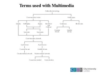
The information associated with the different applications can be either continuous or block-mode • Continuous: The information is played out directly as it is received continuously (called streaming or real-time media) (E.g Audio and video) • Block-mode: The source information is created in a time-independent way and is often stored at the source in, say, a file • When requested it will be transferred across the network and displayed at a time specified by the requesting application (called downloading) (e.g. email consisting of a block of text) Media Types
Communication Modes • Simplex: The information associated with the application flows in one direction only. • Half-Duplex: Information flows in both directions but alternatively (two-way alternative). • Duplex: Information flows in both directions simultaneously (Two-way simultaneous).
Communication Modes • Broadcast: The information output by a single node is received by all the other nodes connected to the same network • Multicast: The information output by the source is received by only a specific subset of the nodes (Latter form known as multicast group)
Communication mode Examples • In half-duplex and duplex communications, the bit rate associated with the flow of information in each direction can be equal (symmetric) or different (asymmetric). • Video Telephony – Symmetric duplex communication • Web browsing – Asymmetric half-duplex mode (as different bit rates for downloading and uploading)
Network Types (Circuit-mode) • This operates in a time-dependent manner and comprises an interconnected set of switching offices/exchanges to which the subscriber terminals/computers are connected
Step1: The source must set up the connection first through the network Step2: Each subscriber terminal has a unique network wide address and to make a call the source first enters this number of the intended communication partner Step3: The local switching office uses this number to set up a connection. Depending on the availability of the destination the connection will be estabilished Step4: Finally at the end of information exchange the call will be terminated by the source or the destination Circuit-mode- Operational Principle
Signalling messages – The messages associated with the setting up and clearing of a connection • Call/Connection setup delay – The delay associated with the connection procedures • Examples of Circuit-mode operation – PSTN and ISDN • PSTN – setup delay varies from fraction of a second to few seconds for international connections • ISDN – setup delay ranges from tens ofmilliseconds through to several hundred milliseconds Circuit-mode- Terminology
There are two types of packet-mode network • - Connection Oriented (CO) Packet mode PSE: Packet Switching Exchanges • As the name implies a connection is established prior to information interchange • The connection utilizes only a variable portion of the bandwidth of each link and known as virtual circuit (VC)
To set up a VC the source terminal sends a call request control packet to the local PSE which in addition to the source and destination addresses holds a short identifier known as virtual circuit identifier (VCI) • Each PSE maintains a table that specifies the outgoing link to use to reach the network address • On receipt of the call request the PSE uses the destination address within the packet to determine the outgoing link • The next free identifier (VCI) for this link is selected and two entries are made in the routingtable Packet mode – Operational Principle
Packet mode – Connectionless • In connectionless network, the establishment of a connection is not required and they can exchange information as and when they arrive • Each packet must carry the full source and destination address in its header in order for each PSE to route the packet onto the appropriate outgoing link (router term used rather than PSE)
In both types each packet is stored in a memory buffer and a check is performed to determine if any transmission errors are present in the received message. (i.e 0 instead of a 1 or vice versa) • If an error is detected then the packet is discarded known as best-effort service. • All packets are transmitted at the maximum link bit rate • As packets may need to use the same link to transfer information an operation known as store-and-forward is used. Packet mode – Summary
The sum of the store and forward delays in each PSE/router contributes to the overall transfer delay of the packets and the mean of this delay is known as the mean packet transfer delay. • The variation about the mean are known as the delay variation or jitter • Example of connectionless mode – Internet • Examples of connection oriented network – X.25 (text) and ATM (multimedia) Packet mode – Summary
Multipoint conferencing is implemented in one of two ways • - Centralized mode • - Decentralized mode • Centralized mode • This mode is used with circuit switched networks such as PSTN and ISDN Multipoint Conferencing
Multipoint Conferencing – Centralized mode • With this mode a central server is used • Prior to sending any information each terminal needs to set up a connection to the server • The terminal then sends the information to the server. • The server then distributes this information to all the other terminals connected in the conference
Multipoint Conferencing – Decentralized mode • The decentralized mode is used with packet-switched networks that support multicast communications • E.g – LAN, Intranet, Internet
Decentralized mode Operation • The output of each terminal is received by all the other members of the conference/multicast group • Hence a conference server is not required and it is the responsibility of each terminal to manage the information streams that they receive from the other members
Hybrid Mode • This type of mode is used when the terminals are connected to different network types • In this mode the server determines the output stream to be sent to each terminal
Network Quality of Service parameters: Operational parameters associated with a communication channel through a network that determine the suitability of the channel in relation to its use for a particular application • Circuit-switched network: Bit Error Rate (BER) is the probability of a bit being corrupted during its transmission in a defined time interval. The transmission delay is determined by the bit rate used plus the codes (network interfaces) and propagation delay of the digital signal • Packet-switched network: Mean packet transfer rate is a measure of the average number of packets transferred per second. Mean Packet Error Rate (PER) is the probability of a received packet containing one or more bit errors Network Qos
Most networks (circuit and packet switched) provide an unreliable service which is also known as a best-try or best-effort service • If the application accepts only error free blocks then it is necessary for the sending terminal to divide the source information into blocks of a defined maximum size and the destination to detect any missing blocks • When a block is missing then the destination must request for a copy of the block from the source. The service is then called a reliable service Network Qos
Application Qos • Transmission of a constant bit rate stream over a packet switched network • The startup delay defines the amount of time that elapses between an application making a request to start a session and the confirmation being received at the destination
Application Qos • To transfer a large file from the server to your home computer using the packet switched (PW) and circuit switched (CS) networks • - PSTN (28.8kbps) and ISDN (64/128kbps) operate in CS mode and provide constant bit rate channel • - Cable modem operate in PS mode and the bit rate of the shared channel is 27Mbps
Application Qos • Assuming the file size is 100Mbits, the minimum time to transmit the file using the different Internet access modes is: • - PSTN and 28.8 kbps modem: 57.8 minutes • - ISDN at 64 kbps: 26 minutes • - ISDN at 128 kbps: 13 minutes • - cable modem at 27 Mbps: 3.7 seconds
Application Qos • The application quality of service is different from the network QoS • For example in an application involving images the parameters may include a minimum image resolution and size while a video may include the digitization format and the refresh rate
Application QoS - Parameters • The required bit rate or mean packet transfer rate • The maximum startup delay • The maximum end-to-end delay • The maximum delay variation/jitter • The maximum round-trip delay
Application Qos • To overcome the effect of jitter a technique known as buffering is used • The effect of jitter is overcome by retaining a defined number of packets in a memory buffer at the destination before playout of the information bit stream is started
In order to determine whether a particular network can meet the QoS requirements of an Application a number of standard application service classes have been defined • Each service class has an associated set of QoS parameters defined • For networks that support different service classes ( i.e internet), the packets relating to each class are assigned a different priority • Real time streams have higher priority than packets relating to email Application QoS - Summary
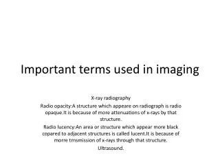
Multimedia Information Representation • Multimedia Information is stored and processed within a computer in a digital form • Codeword: Combination of a fixed number of bits that represents each character, in the case of textual information • analogue signal: Signal whose amplitude (magnitude of the sound/image intensity) varies continuously with time • Signal encoder: Electrical circuit used for the conversion of an analogue signal into a digital form • Signal decoder: Electrical circuit that converts stored digitized samples into time-varying analogue form
analogue Signals • As mentioned earlier the amplitude of the signal varies continuously with time • The Fourier analysis can be used to show that any time varying signal is made up of infinite number of single-frequency sinusoidal components • The range of frequencies of the sinusoidal components that make up the signal is called the signal bandwidth • Speech bandwidth: 50Hz – 10kHz • Music Bandwidth: 15Hz – 20kHz
analogue Signals –Signal Properties • To transmit an analogue signal through a network the bandwidth of the transmission channel should be equal to or greater than the signal bandwidth • If the bandwidth of the channel is less than the signal bandwidth than channel is called the bandlimiting channel
Encoder Design • The Encoder consists of bandlimiting filter and an analogue-to-digital converter (ADC) ( comprising sample and hold + quantizer)
Encoder Design • Bandlimiting filter: Removes the selected higher frequency components from the source signal • Sample and hold Circuit: Samples amplitude of the filtered signal at regular intervals and holds the sampled amplitudes between samples • Quantizer: Converts the samples into their corresponding binary form
Encoder Design – Data representation • The most significant bit of the codeword represents the sign of the sample • A binary 0 indicates a positive value and a binary 1 indicates a negative value • The signal must be sampled at a much higher rate than the maximum rate of change of the signal amplitude • The number of quantization levels should be as large as possible to represent the signal accurately
Sampling Rate • Nyquist sampling theorem: To obtain an accurate representation of a time-varying analogue signal, its amplitude must be sampled at a minimum that is equal to or greater than twice the highest sinusoidal frequency component that is present in the signal • Nyquist rate is represented either in Hz or more correctly in samples per seconds (sps) • Antialiasing filter: Another name for bandlimiting filter. Since it passes frequencies that are within the Nyquist rate
Alias signal generation due to undersampling • In reality the transmission channel used often has a lower bandwidth • To avoid distortion the source signal is first passed through the BLF which is designed to pass only the frequency components that are within the channel bandwidth • This avoids alias signals caused by undersampling
Quantization Intervals • Representation of the analogue samples require an infinite number of digits
Quantization Intervals • Three bits are used to represent each sample ( 1 bit for the sign and two bits to represent the magnitude) • If Vmaxis the maximum positive and negative signal amplitude and n is the number of binary bits used then the quantization interval, q, is defined as • q = 2Vmax/ 2n • A signal anywhere within the quantization interval will be represented by the same binary codeword • Each cordword is at the centre of the corresponding quantization interval • Therefore a difference of q/2 from the actual signal level is present. This difference is known as the quantization error
Quantization noise polarity • Quantization error is the difference between the actual signal amplitude and the corresponding nominal amplitude (also known as quantization noise since values vary randomly)
Dynamic Range • With high-fidelity music it is important to be able to hear very quiet passages without any distortion created by quantization noise • Dynamic range is defined as the ratio of the maximum signal amplitude to the minimum. • D = 20 log10 (Vmax/Vmin) dB
Decoder Design Encoder+decode= Codec • A signal decoder is an electronic circuit that performs the conversion prior to their output back again into their analogue form through a digital-to-analogue converter and a low pass filter • Low-pass filter: Only passes those frequency components that were filtered through the bandlimiting filter in the encoder
Text • Unformatted text: Known as plain text; enables pages to be created which comprise strings of fixed-sized characters from a limited character set • Formatted Text: Known as richtext; enables pages to be created which comprise of strings of characters of different styles, sizes and shape with tables, graphics, and images inserted at appropriate points • Hypertext: Enables an integrated set of documents (Each comprising formatted text) to be created which have defined linkages between them
Unformatted Text – The basic ASCII character set • Control characters • (Back space, escape, delete, form feed etc) • Printable characters • (alphabetic, numeric, and punctuation) • The American Standard Code for Information Interchange is one of the most widely used character sets and the table includes the binary codewords used to represent each character (7 bit binary code)
Unformatted Text – Supplementary set of Mosaic characters • The characters in columns 010/011 and 110/111 are replaced with the set of mosaic characters; and then used, together with the various uppercase characters illustrated, to create relatively simple graphical images
Unformatted Text – Examples of Videotext/Teletext • Although in practice the total page is made up of a matrix of symbols and characters which all have the same size, some simple graphical symbols and text of larger sizes can be constructed by the use of groups of the basic symbols
Formatted Text • It is produced by most word processing packages and used extensively in the publishing sector for the preparation of papers, books, magazines, journals and so on.. • Documents of mixed type (characters, different styles, fonts, shape etc) possible. • Format control characters are used