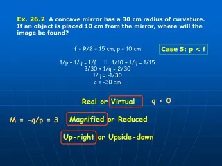
Download
1 / 17
210 likes | 522 Vues
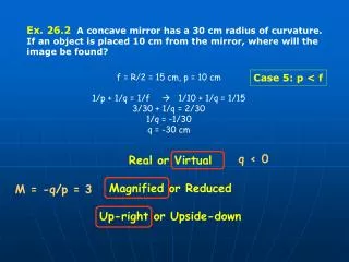
Draw the half development of a hemispherical bowl of radius 3 cm by any method. Divide into meridian sections – Gore development. 10. 8. 6. The approximate method is used Divide the top view into sectors as shown

E N D
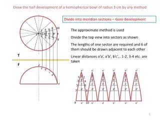
Draw the half development of a hemispherical bowl of radius 3 cm by any method Divide into meridian sections – Gore development 10 8 6 The approximate method is used Divide the top view into sectors as shown The lengths of one sector are required and 6 of them should be drawn adjacent to each other Linear distances o’a’, a’b’, b’c’,…1-2, 3-4 etc. are taken 4 2 a b c d e o 1 3 5 7 9 T F o’ o’ o’ o’ o’ o’ o’ a’ a’ a’ a’ a’ a’ a’ b’ 1 2 c’ b’ b’ b’ b’ b’ b’ 3 4 d’ c’ c’ c’ c’ c’ c’ 5 6 d’ d’ d’ d’ d’ d’ 7 8 e’ 9 10 e’ e’ e’ e’ e’ e’
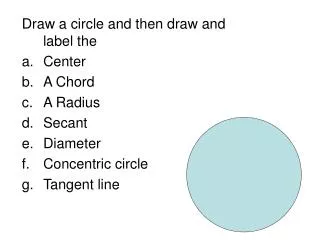
Concept of Principal lines of a plane All the points lie on a straight line representing the edge of the plane Point view C B TL A1 T • Draw a line on the plane in one view parallel to the other plane. • The corresponding projection in the other plane will give the true length. A T F A’ C’ Principal line B’
Principal lines: Lines on the boundary or within the surface, parallel to the principal planes of projection -They can be frontal lines (parallel to frontal plane)-Horizontal lines (parallel to top plane) Frontal line (parallel to frontal plane) b True length b l a f l a c T c T F c’ F c’ a’ l’ f’ a’ True length b’ l’ Horizontal line (parallel to top plane) b’
To obtain the edge view of a plane x1 b1 Edge view of the plane b True length a1 l a c1 c -Draw a principle line in one principle view and project the true length line in the other principle view -With the reference line perpendicular to the true length line, draw a primary auxiliary view of the plane, to obtain the edge view Distances: a1, b1, c1 from x1y1 = a’, b’, c’ from xy respectively T y1 x y c’ F l’ a’ b’ Horizontal line (parallel to top plane)
A cylinder, diameter of base 30 mm is standing on its base on ground and positioned in third quadrant. The position of center of upper base is O1(25, 30, 25) and the center of the lower base is O2(25, 30, 75). Points A (0,60,45),B(15, 5, 70) and C(65, 35, 35) lie on a plane that cuts the cylinder in two parts. Draw the two orthographic views of the cut portion of the cylinder. The coordinates of any point (x, y, z) represent distances measured from left profile plane, frontal plane and top plane respectively. Cutting plane is oblique y Generator lines A C 30 • Draw lines across the Top View(generator lines) starting from one corner of the plane upto the opposite side (AB). • Project the intersection points between the generator lines and the side (AB) into the Front View • Join these points with the corresponding corner C in the FV • Project points of intersection of the section and the generator lines from the TV into the FV • Two generator lines should be tangent to the section in the TV to get the width of the section in the FV 20 T 10 B x 10 20 30 10 F O1 20 30 30 C A B O2 z
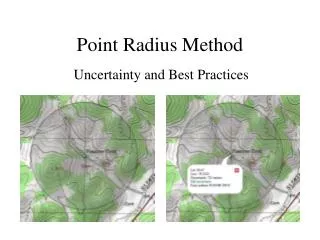
y A cylinder, diameter of base 30 mm is standing on its base on ground and positioned in third quadrant. The position of center of upper base is O1(25, 30, 25) and the center of the lower base is O2(25, 30, 75). Points A (0,60,45),B(15, 5, 70) and C(65, 35, 35) lie on a plane that cuts the cylinder in two parts. Draw the two orthographic views of the cut portion of the cylinder. The coordinates of any point (x, y, z) represent distances measured from left profile plane, frontal plane and top plane respectively. Principle line A C 30 • AUXILIARY VIEW METHOD • Draw the top and front views using the given coordinates • Draw the auxiliary view in order to obtain the edge view of the plane passing through the cylinder • From this view, project back in the Top and Front views, the points of intersection of plane and cylinder. 20 10 x B 10 20 30 10 O1 20 30 C A True length line A z This color is used for projecting the top, front and auxiliary views This color is used to project back the points of intersection O2 C B B 30
Auxiliary view of TRUE SHAPE of a plane always gives an EDGE VIEW True shape is the auxiliary view obtained from the edge view x1 b4 Edge view of the plane b1 b True length b2 a1 c4 l a a c1 c a4 True shape and dimensions of the plane T y1 y x c2 a2 F c’ b3 l’ c3 a’ a3 b’ Edge view of plane Horizontal line (parallel to top plane)
To obtain the angle of inclination and true shape of a plane True shape is the auxiliary view obtained from the edge view x1 b1 Edge view of the plane b True length b2 a1 l a SECONDARY AUXILIARY VIEW a c1 c y1 T x y a2 c’ c2 F b True shape and dimensions of the plane l’ a’ parallel b’ Obtain edge views of the lines as discussed earlier a is the inclination with top plane b is the inclination with frontal plane Horizontal line (parallel to top plane)
x2 Point view of line Point on line at shortest distance a2, b2 Shortest distance between the point and line in True Length b1 c1 a1 Point p2 p1 x1 y2 • TO OBTAIN THE SHORTEST DISTANCE BETWEEN A POINT AND A LINE • Obtain the true length (shown in red) of a line by drawing the primary auxiliary view of the line with the reference line parallel to the original view and project the point also into the view • Draw the point view of the line by obtaining the secondary auxiliary view of the line with the reference line perpendicular to the line • The distance from the point view of the line to the point is the shortest distance between the line and point a y1 c b p T y x F p’ c’ a’ b’
Primary auxiliary view c1 DISTANCE BETWEEN 2 LINES TL Secondary auxiliary view d1 d2, c2 a1 Required distance b1 c a2 b2 b * Point can be projected back into the other planes a d T • Find the true length of one of the lines and project its point view using auxiliary plane method • Project the other line also in each view • The perpendicular distance between the point view of one line and the other line is the required shortest distance between the two lines F b’ a’ c’ d’
c3 b3 TERTIARY AUXILIARY VIEW TRUE LENGTH OF BOTH LINES Parallel d3 True Angle between the two lines x3 x2 c2 a3 d2 y3 a2 ,b2 ANGLE BETWEEN TWO INTERSECTING LINES Point view of one line True length SECONDARY AUXILIARY VIEW b1 y2 Draw primary auxiliary view such that one line (blue) shows in True Length Draw secondary auxiliary view with reference line perpendicular to the True Length of the line to get the point view of the line Draw a tertiary auxiliary view with reference line parallel to the other line (light green) in order to get its True Length Since the secondary auxiliary view had the point view of the first line, the tertiary auxiliary view will have the True Length of the first line also (blue) PAV y1 c1 d1 b a1 Parallel x1 d c T a y x F d’ a’ c’ b’
Angle between 2 planes Line of intersection of the 2 planes (here it is True Length) Basically you have to view the two planes in such a way that the line of intersection of the planes is perpendicular to the plane of view (point view) x1 f1, e1 e f PAV-Edge view of both planes d Angle between the 2 planes c c1, d1 b1, a1 a b T • Obtain an auxiliary view such that the reference line is perpendicular to the True Length of the line of intersection of the planes • In this case, the intersection line is parallel to both principle planes and hence is in True Length in both front and top views • Both planes will be seen as edge views in the auxiliary view. • The angle between the edge views is the angle between the planes x y F b’ a’ y1 c’ d’ e’ f’
A decoration piece is being hung from the ceiling by three chains at points A, B and C as shown. Find the true lengths of the chains and true angle between AO and BO and between AO and CO. (Dimensions are given in m.) True length (Principal line) of AB True lengths of chains AO and BO b2 0.6 b c 0.2 True angle between AO and BO a a2 o a1, b1 b’ c’ a’ o2 Secondary auxiliary view showing true shape and dimensions of triangle AOB Primary auxiliary view to obtain edge view of triangle AOB o1 o’
Figure shows the Top and Front views of an oblique square pyramid with base abcd and apex o. Find the true lengths of the edges by any method and draw the true shape of the face oab. What is the angle that the plane makes with the horizontal plane? -Identify the faces in the Front and Top views having true shape and/or edge views.
In the Front and Top views, identify the planes having an edge view and/or true shape. Draw the true shape of the plane ADC. What is the angle between planes ADC and ABC?