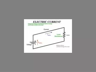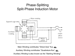
Resistance-Start Split-Phase Motor
Resistance-Start Split-Phase Motor. R = R ext. Graphical Analysis. I aux decreases with increasing R ext. angle α increases with increasing R ext. Locked-rotor Torque “peaks” for an “optimal” value of R ext . Phase displacement angle α is between 25° and 30°.

Resistance-Start Split-Phase Motor
E N D
Presentation Transcript
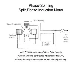
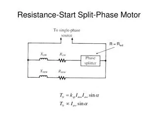
Resistance-Start Split-Phase Motor R = Rext
Graphical Analysis Iaux decreases with increasing Rext angle α increases with increasing Rext Locked-rotor Torque “peaks” for an “optimal” value of Rext . Phase displacement angle α is between 25° and 30°.
Practical Resistance-Start Motor “Centrifugal” switch or TRIAC Closed (shorted) when the motor is at rest Opens when motor speed is 75% – 85% of synchronous speed
Capacitor-Start Split-Phase Motor Develop a larger value of Iaw sinα, and, hence, a larger locked-rotor torque Phase-displacement angle between 75° and 85°
Torque-Speed Characteristic Higher Starting Torque Same Running Torque as before
Permanent-Split Capacitor Motor • Uses a permanently-connected auxiliary circuit containing a capacitor. • Smoother and quieter operation than resistor or capacitor starting motor • Speed control by autotransformer across the line, or external resistor or reactor (inductor) in series with the main or auxiliary winding (or both).
Permanent-Split Capacitor Motor “Permanent” Capacitor Speed control by autotransformer
Two-Value Capacitor Motor Small capacitor for running main Large capacitor for starting auxiliary Centrifugal switch
Example 6-2 • Using the motor from Example 6-1, determine the capacitance required in series with the auxiliary winding in order to obtain a 90° phase displacement between the current in the main winding and the current in the auxiliary winding at locked-rotor and the locked-rotor torque in terms of the machine constant.
Example 6-2 continued • From Example 6-1
Graphical Analysis Auxiliary winding current increases then decreases with increasing capacitive reactance (why?) Angle α increases with increasing capacitive reactance Locked-rotor torque “peaks” for the optimal value of capacitive reactance. The resulting phase displacement angle is approximately 75°