Microcontroller ( C) vs. Microprocessor ( P)
Microcontroller ( C) vs. Microprocessor ( P). C intended as a single chip solution, P requires external support chips (memory, interface) C has on-chip non-volatile memory for program storage, P does not.

Microcontroller ( C) vs. Microprocessor ( P)
E N D
Presentation Transcript
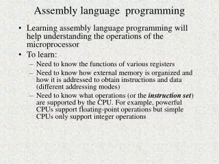
Microcontroller (C) vs. Microprocessor (P) • C intended as a single chip solution, P requires external support chips (memory, interface) • C has on-chip non-volatile memory for program storage, P does not. • C has more interface functions on-chip (serial interfaces, Analog-to-Digital conversion, timers, etc.) than P • C does not have virtual memory support (I.e, could not run Linux), while P does. • General purpose Ps are typically higher performance (clock speed, data width, instruction set, cache) than Cs • Division between Ps and Cs becoming increasingly blurred V 0.7
PIC 18Fxx2 C V 0.7
Inst. Reg PIC18 Simplified Block Diagram RAM File Registers 16 Program Counter address 21 Data 12 address 8 Program Memory,non-volatile, up to 2M bytes (1M x 16) 8 bitops W 8 DOUT 8 8 Two operand instructions have the Working Register (w reg) as one operand, and memory or data in the current instruction as the second operand. The destination can be either be w reg or file registers. The instruction register contains the machine code of the instruction currently being executed. ALU 8 Multiplier not shown V 0.7
Memory Organization Memory on the PIC is split into two types: Program Memory and Data Memory . PIC18 instructions are stored in program memory, which is non-volatile (contents are retained when power is lost). A PIC18 instruction is 16-bits wide ( 2 bytes). PIC18F242 program memory is 8K x 16 (16 Kbytes); the PIC18 architecture can support up to 1M x 16 (2M bytes) of program memory. PIC18 data is stored in data memory, also known as the file registers, and is a maximum size of 4K x 8. Data memory is volatile (contents are lost when power is lost). V 0.7
Data Memory Organization Data Memory is split into banks of 256 locations (0x100 locations) Data Memory Map GPR – General Purpose Registers SFR - Special Function Registers 0x00 0x000 0x7F Access Ram (GPR) 0x07F Bank 0 0x80 0x080 Access Ram GPR 0xFF 0x0FF 0x00 0x100 Bank 1 GPR 0x00 Access Ram Low 0xFF 0x1FF (GPR) 0x7F 0x00 0x200 0x80 Access Ram High Bank 2 GPR 0xFF 0x2FF 0xFF (SFR) 0x00 0xF00 GPR 18F242 has banks 0, 1, 2 and SFRs (0xF80 – 0xFFF). Other versions implement more banks. 0xF7F Bank 15 0xF80 0xFF SFR 0xFFF V 0.7
Accessing Data Memory The machine code for a PIC18 instruction has only 8 bits for a data memory address which needs 12 bits. The Bank Select Register (BSR) supplies the other 4 bits. 0x00 PIC18 instruction 0x7F Access Ram (GPR) Bank 0 0x80 OP 8-bit address GPR 0xFF 0x00 Bank 1 GPR Bank Select Register 0xFF lower 4 bits 0x00 Bank 2 GPR 0xFF 0x00 GPR 12-bit address Bank 15 0xFF SFR V 0.7
Special Function Registers (SFRs), General Purpose Registers (GPRs) The Bank Select Register and the W register (working register) are examples of Special Function Registers (SFR). There are many SFRs in the PIC18 – they are used as control registers and data register for processor subsystems (like the serial interface, or the analog-to-digital converter). We will cover their use and names as we need to. SFRs live in the address range 0xF80 to 0xFFF in data memory. See section 4.9.2 of the datasheet for a complete list of SFRs. General Purpose Registers (GPRs) are locations in data memory that can be used for storage of temporary data; they are not used by the processor subsystems. V 0.7
Instruction Operands An operandis the data that an instruction operates on. Instructions in the PIC18 have either zero operands (require no data), one operand, or two operands The ‘out 5’ instruction in the Student ID CPU is an example of a one operand instruction. Examples of two operand instructions are addition, subtraction. Examples of one operand instructions are increment, decrement. Examples of no operand instructions SLEEP (halt processor, goto low power mode), CLRWDT (clear watchdog timer). V 0.7
Two Operand Instructions One form of a two operand instruction is below. Note that one of the source operands is overwritten! Used by most arithmetic/logical operations operand2 destination operand1 operation src1 | src2 src1 op src2 eg. A A + B eg. B A - B Another form, used by the ‘move’ instructions: destination source dest src V 0.7
movwf Instruction form “Write contents of W register to data memory location floc”. General form: movwf floc[,a] floc (w) floc is a memory location in the file registers (data memory) w is the working register a is data memory access bit, ‘ACCESS’(0) use Access Bank -- ignore Bank Select Register (BSR), ‘BANKED’(1), use BSR. (will talk more about this later), [a] means optional usage. When floc is destination, means “modify memory location floc”. movwf 0x70 0x70 (w) V 0.7
movwf Instruction Execution Assume the following Memory/Register contents before execution: W = 0x2A (unaffected) W = 0x2A written Location Contents modified BEFORE AFTER movwf 0x070 movwf 0x070 V 0.7
movwf Instruction Format see table 20-2 in PIC18 datasheet B B B B B B B B B B B B B B B B1 1 1 1 1 1 0 0 0 0 0 0 0 0 0 05 4 3 2 1 0 9 8 7 6 5 4 3 2 1 0 movwf floc [,a] 0 1 1 0 1 1 1 a f f f f f f f f floc (w) ‘ffffffff’ lower 8-bits of floc address a = 1 use Bank Select Register (BANKED); a = 0 ignore BSR, just use ACCESS BANK machine code movwf 0x070, 0 0110 1110 0111 0000 = 0x6e70 movwf 0x070, 1 0110 1111 0111 0000 = 0x6f70 V 0.7
The Bank Select Register again.... movwf 0x070, 1 also written as: movwf 0x070, BANKED The execution of the above instruction depends on the value in the Bank Select Register. If BSR = 0, then location 0x070 is modified.If BSR = 1, then location 0x170 is modified.If BSR = 2, then location 0x270 is modified....etc. movwf 0x070, 0 also written as: movwf 0x070, ACCESS The execution of the above instruction does NOT depend on the value in the Bank Select Register, only the 8 bits in the machine code is used for the address location. Location 0x070 is always modified. V 0.7
What the heck is the Access Bank? The lower 128 locations (0x0 – 0x07F) and upper 128 locations (0xF80 – 0xFFF) as a group is called the Access Bank. The ‘a’ bit (access bit) in the machine code can provide access to these locations without regard to the BSR. This is important because the SFRs live in 0xF80 – 0xFFF (Bank 15). If the ‘a’ bit was NOT included in instructions, then anytime we wanted to access a special function register (which happens a LOT), we would have to change the value of the BSR to 0xF (Bank 15). V 0.7
Rules for the ‘access’ bit in instructions We will use the following rules for the value of the ‘a’ (Access) bit in machine code produced for instructions that contain a data memory address (these assumptions used by the MPLAB assembler) • If the data memory address is between 0x000 – 0x07F or between 0xF80 – 0xFFF, assume the ‘a’ bit is a ‘0’ (ignore the BSR). • If the data memory address is between 0x080 – 0xF7F, assume the ‘a’ bit is a ‘1’ (use the BSR). We will NEVER write: movf 0x070, BANKED Always either “movf 0x070” (assume ACCESS, a = 0) or “movf 0x170” (assume BANKED, a = 1). V 0.7
Machine Code Examples for movwf B B B B B B B B B B B B B B B B1 1 1 1 1 1 0 0 0 0 0 0 0 0 0 05 4 3 2 1 0 9 8 7 6 5 4 3 2 1 0 movwf floc [,a] 0 1 1 0 1 1 1 a f f f f f f f f floc (w) mnemonic machine code movwf 0x070 0110 1110 0111 0000 = 0x6e70 (a=0) movwf 0x170 0110 1111 0111 0000 = 0x6f70 (a=1) movwf 0x270 0110 1111 0111 0000 = 0x6f70 (a=1) movwf 0xF90 0110 1110 1001 0000 = 0x6e90 (a=0) We will not specify the ‘a’ bit on instruction mnemonics. V 0.7
Changing the Bank Select Register WHOA! The instruction mnemonics are different, but the machine code is the same! That is because machine code only uses lower 8-bits of the address!!!! mnemonic machine code 0x6f70 movwf 0x170 movwf 0x270 0x6f70 For this to work, BSR must be 0x1! movwf 0x170 movwf 0x270 For this to work, BSR must be 0x2! By default (after processor reset), BSR = 0x0!!!! V 0.7
movlb Instruction B B B B B B B B B B B B B B B B1 1 1 1 1 1 0 0 0 0 0 0 0 0 0 05 4 3 2 1 0 9 8 7 6 5 4 3 2 1 0 movlb k 0 0 0 0 0 0 0 1 0 0 0 0 k k k k BSRk Move 4-bit literalk into BSR (only 16 banks, hence, only 4-bits) mnemonic machine code movlb 2 0000 0001 0000 0010 = 0x0102 Example usage: Selects bank 2 Causes location W to be written to location 0x270 movlb 2 movwf 0x270 V 0.7
Move Register (movf) Copies a value from data memory to w or back to data memory. B B B B B B B B B B B B B B B B1 1 1 1 1 1 0 0 0 0 0 0 0 0 0 05 4 3 2 1 0 9 8 7 6 5 4 3 2 1 0 movf floc, [, d[, a] d(floc) 0 1 0 1 0 0 d af f f f f f f f ‘fffffff’ lower 8-bits of floc address ‘d’: 0 = w reg, 1 = f Machine code Instruction 0x501D movf 0x01D,w w (0x01D) 0x521D movf 0x01D,f 0x1D (0x01D) The second example looks useless as it just moves the contents of a memory location back onto itself. However, it is useful, as will be seen later. V 0.7
Copying Data Between Banks Assume you want to copy data from location 0x1A0 to location 0x23F. Location 0x1A0 is in bank1, location 0x23F is in bank 2. The HARD way: movlb 0x1 ; select bank1 movf 0x1A0,w ; w (0x1A0) movlb 0x2 ; select bank2 movwf 0x23F ; 0x23f (w) The EASY way: movff 0x1A0,0x23F ; 0x23f (0x1A0) The movff instruction copies the contents of a source location to a destination location. V 0.7
movff Instruction B B B B B B B B B B B B B B B B1 1 1 1 1 1 0 0 0 0 0 0 0 0 0 05 4 3 2 1 0 9 8 7 6 5 4 3 2 1 0 movff fs, fd 1 1 0 0 f f f f f f f f f f f f (src) fd (fs) 1 1 1 1 f f f f f f f f f f f f (dest) Move contents of fs to fd Machine code Instruction movff 0x1A0,0x23F ; 0x23f (0x1A0) 0xC1A0 0xF23F Requires two instruction words (4 bytes). Only movff, goto, call, lfsr instructions take two words; all others take one word. V 0.7
The addwf instruction General form: addwf floc[, d[, a]d (floc) + (w) floc is a memory location in the file registers (data memory) w is the working register d is the destination, can either be the literal ‘f’(1, default) or ‘w’(0) a is data memory access bit (floc) means “the contents of memory location floc” addwf 0x070,w w (0x070) + (w) addwf 0x070,f 0x070 (0x070) + (w) V 0.7
Data Memory addwf Examples Location contents 0x058 0x2C Assume data memory contents on right w register contains 0x1D 0x059 0xBA 0x05A 0x34 0xD3 0x05B Execute: addwf 0x059, w w (0x059) + (w) w = (0x059) + (w) = 0xBA + 0x1D = 0xD7 After execution w = 0xD7, memory unchanged. Execute: addwf 0x059, f 0x059 (0x059) + (w) 0x059 = (0x059) + (w) = 0xBA + 0x1D = 0xD7 After execution, location 0x059 contains 0xD7, w is unchanged. V 0.7
addwf instruction encoding B B B B B B B B B B B B B B B B1 1 1 1 1 1 0 0 0 0 0 0 0 0 0 05 4 3 2 1 0 9 8 7 6 5 4 3 2 1 0 addwf floc[, d[, a] 0 0 1 0 0 1 d a f f f f f f f f ‘fffffff’ lower 8-bits of floc address ‘d’: 0 = w reg, 1 = f Machine code Instruction 0x2659 addwf 0x059, f 0x2459 addwf 0x059, w ALWAYS specify these on your instructions!!!!!!! I will NOT assume a default value during grading. V 0.7
subwf Instruction B B B B B B B B B B B B B B B B1 1 1 1 1 1 0 0 0 0 0 0 0 0 0 05 4 3 2 1 0 9 8 7 6 5 4 3 2 1 0 subwf floc[, d[, a] d (floc) - (w) 0 1 0 1 1 1 d a f f f f f f f f ‘fffffff’ lower 8-bits of floc address ‘d’: 0 = w reg, 1 = f Machine code Instruction 0x5E59 subwf 0x059, f 0x5C59 subwf 0x059, w V 0.7
Data Memory subwf Examples Location contents 0x058 0x2C Assume data memory contents on right w register contains 0x1D 0x059 0xBA 0x05A 0x34 0xD3 0x05B Execute: subwf 0x059, w w (0x059) - (w) w = (0x059) - (w) = 0xBA - 0x1D = 0x9D After execution w = 0x9D, memory unchanged. Execute: subwf 0x059, f 0x059 (0x059) – (w) 0x059 = (0x059) - (w) = 0xBA - 0x1D = 0x9D After execution, location 0x059 contains 0x9D, w is unchanged. V 0.7
Move literal to w (movlw) The previous example assumed that w contained a value of 0x1D. How did this get into w in the first place ? B B B B B B B B B B B B B B B B1 1 1 1 1 1 0 0 0 0 0 0 0 0 0 05 4 3 2 1 0 9 8 7 6 5 4 3 2 1 0 movlw k w k 0 0 0 0 1 1 1 0 k k k k k k k k “kkkkkkkk” 8-bit literal, loaded into w register Machine code Instruction 0x0E1D movlw 0x1D Note that the instruction word contains the 8-bit constant, not data memory address. V 0.7
Increment (incf) B B B B B B B B B B B B B B B B1 1 1 1 1 1 0 0 0 0 0 0 0 0 0 05 4 3 2 1 0 9 8 7 6 5 4 3 2 1 0 incf floc[,d,[a] Increment destination by 1 0 0 1 0 1 0 d a f f f f f f f f ‘fffffff’ lower 8-bits of floc address ‘d’: 0 = w reg, 1 = f Machine code Instruction 0x2A59 incf 0x059, f ;0x059 (0x059) +1 0x2859 incf 0x059, w ; w (0x059) + 1 V 0.7
Decrement (decf) B B B B B B B B B B B B B B B B1 1 1 1 1 1 0 0 0 0 0 0 0 0 0 05 4 3 2 1 0 9 8 7 6 5 4 3 2 1 0 decf floc[,d,[a] Decrement destination by 1 0 0 0 0 0 1 d a f f f f f f f f ‘fffffff’ lower 7-bits of floc address ‘d’: 0 = w reg, 1 = f Machine code Instruction 0x0659 decf 0x059, f ;0x059 (0x059) -1 0x0459 decf 0x059, w ; w (0x059) - 1 V 0.7
Inst. Reg How is the instruction register loaded? RAM File Registers 16 Program Counter address 21 Data 12 address 8 Program Memory,non-volatile, up to 2M bytes (1M x 16) 8 bitops W 8 DO 8 8 Program counter contains the address of the current instruction being executed. After reset, first instruction fetched from location 0x0000 in program memory. ALU 8 V 0.7
Goto location (goto) The program counter specifies the location of the current location. How is this changed? B B B B B B B B B B B B B B B B1 1 1 1 1 1 0 0 0 0 0 0 0 0 0 05 4 3 2 1 0 9 8 7 6 5 4 3 2 1 0 goto k PC[20:1] k 1 1 1 0 1 1 1 1 k7 k k k k k k k0 1 1 1 1 k19 k k k k k k k k k k k k is 20 bit value that specifies the instruction WORD location (take byte location, divide by 2 – all words start at location divisible by 2). Machine code Instruction 0xEF04 goto 0x0208 0xF001 The next instruction is fetched from the target address. This instruction take TWO instruction words (4 bytes). Byte location, has to be even. k = 0x208 >> 1 (shift right is 2) = 0x104 V 0.7
A Simple Program In this class, will present programs in C form, then translate (compile) to PIC assembly language. C Program equivalent #define myid 100 unsigned char i,j,k; i = myid; /* myvalue = 100 */ i = i + 1; /* i++, i = 101 */ j = i; /* j is 101 */ j = j - 1; /* j--, j is 100 */ k = j + i; /* k = 201 */ A ‘char’ variable is 8-bits (1 byte) V 0.7
Where are variables stored? When writing assembly language, can use any free data memory location to store values, it your choice. A logical place to begin storing data is in Bank0, locations (0x000-0x0FF). Assign i to0x000, j to 0x001, and k to 0x002. Other choices could be made. V 0.7
C to PIC Assembly 100 in hex. movlw 0x64 movwf 0x000 incf 0x000,f movf 0x000,w movwf 0x001 decf 0x001,f movf 0x000,w addwf 0x001,w movwf 0x002 i = 100; i = i + 1; j = i; j = j - 1; k = j + i; Comments: The assembly language program operation is not very clear. Also, multiple assembly language statements are needed for one C language statement. Assembly language is more primitive (operations less powerful) than C. V 0.7
PIC Assembly to PIC Machine Code • Could perform this step manually by determining the instruction format for each instruction from the data sheet. • Much easier to let a program called an assembler do this step automatically • MPLAB Integrated Design Environment (IDE) is used to assemble PIC programs and simulate them • Simulate means to execute the program without actually loading it into a PIC microcontroller V 0.7
INCLUDE "p18f242.inc" CBLOCK 0x000 ;Register Usage i, j,k ; reserve space ENDC myid equ D'100' ; define myid label org 0 goto main org 0x0200main movlw myid ; w <- 100 movwf i ; i <- w; incf i,f ; i <- i + 1 movf i,w ; w <- i movwf j ; j <- w decf j,f ; j <- j – 1 movf i,w ; w <- I addwf j,w ; w <- w + j movwf k ; k <- w here goto here ; loop forever end mptest.asm This file can be assembled by MPLAB into PIC machine code and simulated. Labels used for memory locations 0x000 (i), 0x001(j), 0x002(k) to increase code clarity V 0.7
Include file that defines various labels for a particular processor. This is an assembler directive, do not start in column 1. Only labels start in column 1. mptst.asm (cont.) INCLUDE "p18f242.inc" ; Register Usage CBLOCK 0x000 ; i, j,k ; reserve space ENDC An assembler directive that reserves space for named variables starting at the specified location. Locations are reserved in sequential order, so i assigned 0x000, j to 0x001, etc. Use these variable names instead of absolute memory locations. An assembler directive is not a PIC instruction, but an instruction to the assembler program. V 0.7
mptst.asm (cont.) An assembler directive that equates a label to a value. The D’100’ specifies a decimal 100. Could have also done: myid equ .100 myid equ 0x64 myid equ H’64’ myid equ D'100' org 0 goto main org 0x0200main An assembler directive that specifies the starting location (origin) of the code after this statement. This places the code beginning at location 0x0000 in program memory. There must always be valid code at location 0 since the first instruction is fetched from here. We will locate our main entry point at 0x0200 to leave free code space between 0x0 and 0x0200 (more on this later). V 0.7
mptst.asm (cont.) The use of labels and comments greatly improves the clarity of the program. It is hard to over-comment an assembly language program if you want to be able to understand it later. Strive for at least a comment every other line; refer to lines ; i = 100; movlw myid ; w <- 100 movwf i ; i <- w; ; i = i+1; incf i,f ; i <- i + 1 ;j = i movf i,w ; w <- i movwf j ; j <- w V 0.7
A label that is the target of a goto instruction. Labels must start in column 1, and are case sensitive (instruction mnemonics are not case sensitive. mptst.asm (cont.) here goto here ; loop forever end A comment An assembler directive specifying the end of the program. All assembly language programs must have an end statement. V 0.7
General MPLAB Comments • See Experiment #2 for detailed instructions on installing MPLAB on your PC and assembling/simulating programs. • The assembly language file must have the .asm extension and must be a TEXT file • Microsoft .doc files are NOT text files • MPLAB has a built-in text editor. If you use an external text editor, use one that displays line numbers (e.g. don’t use notepad – does not display line numbers) • You should use your portable PC for experiments 1-5 in this class, all of the required software is freely available. V 0.7
Clock Cycles vs. Instruction Cycles The clock signal used by a PIC18 to control instruction execution can be generated by an off-chip oscillator, by using an external RC network to generate the clock on-chip, or by connecting a crystal/capacitor network. For the PIC 18Fxx2, the maximum clock frequency is 40 MHz. An instruction cycle is fourclock cycles. A PIC instruction takes 1 or 2 instruction cycles, depending on the instruction (see Table 20-2, PIC 16F87X data sheet). If an instruction causes the program counter to change, that instruction takes 2 instruction cycles. An add instruction takes 1 instruction cycle. How much time is this if the clock frequency is 20 MHz ( 1 MHz = 1.0e6 = 1,000,000 Hz)? 1/frequency = period, 1/20 MHz = 50 ns (1 ns = 1.0e-9 s) Add instruction @ 20 MHz takes 4 * 50 ns = 200 ns (or 0.2 us). By comparison, a Pentium IV add instruction @ 3 GHz takes 0.33 ns (330 ps). A Pentium IV could emulate a PIC faster than a PIC can execute! But you can’t put a Pentium IV in a toaster, or buy one from digi-key for $5.00. Important!!!!!!! V 0.7
Review: Units In this class, units are always used for physical qualities: When a time/frequency/voltage/current quantity is asked for, I will always ask from some units. Values for these quantities in datasheets ALWAYS are given in units. For a frequency of 1.25 KHz, what is the period in s? period = 1/f = 1/(1.25 e3) = 8.0 e –4 seconds Unit conversion= 8.0e-4 (s) * (1e6 s)/1.0 (s) = 8.0e2 s = 800 s V 0.7
PIC18xx2 • Microchip has an extensive line of PIC microcontrollers, of which the PIC18xx2 is the most recent. • The PIC16 is previous version of the PIC, have been several previous generations. • Do not assume that because something is done one way in the PIC18Fxx2, that it is the most efficient method for accomplishing that action. • The datasheet for the PIC18xx2 is found on the class web site. V 0.7
PIC16F87x vs PIC18Fxx2 Features in PIC18 not present in PIC16: 8x8 hardware multiplier, stack push/pop instructions, branch instructions, signed, better support for signed comparisons (V, N flags). Peripherals are essentially the same for both processors. Both processors take 4 clock cycles for 1 instruction cycle. V 0.7
What do you need to know? • Understand the operation of movelw, addwf, incf, decf, goto, movlb, movff instructions • Understand data memory organization • Be able to convert PIC assembly mnemonics to machine code and vice-versa • Be able to compile/simulate a PIC assembly language program in MPLAB • Understand the relationship between instruction cycles and machine cycles V 0.7