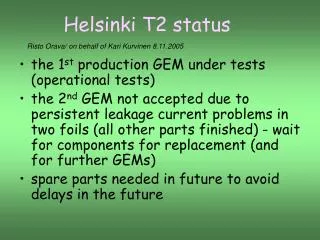
Helsinki T2 status
The first production of Gas Electron Multiplier (GEM) foils is undergoing operational testing. The initial GEM is approved, while the second is rejected due to leakage current issues. Spare parts are essential to prevent future delays. Characterization involves leakage current measurements, visual inspections, and optical scanning. Measurements show that two of twelve foils were initially deemed faulty. A graphical display system was incorporated to detect instability. Overall, foil quality has significantly improved, with optical scanning revealing more defects than visual inspection.

Helsinki T2 status
E N D
Presentation Transcript
Helsinki T2 status Risto Orava/ on behalf of Kari Kurvinen 8.11.2005 • the 1st production GEM under tests (operational tests) • the 2nd GEM not accepted due to persistent leakage current problems in two foils (all other parts finished) - wait for components for replacement (and for further GEMs) • spare parts needed in future to avoid delays in the future
Characterisation of GEM foils: • leakage current measurements • visual inspection • optical scanning
Leakage current measurements of GEM foils • the four segments (A,B,C & D, see Fig.) of the GEM foils are measured separately by Picoamp /Voltage source device (Keithley 487). • leakage currents are measured three times during the assembly (the foil before and after framing, then after gluing into a stack). 3 x 3 foils x 4 36 measurements / detector • current limited by 100 MW resistor (corresponding to the max current of 5 mA at 500V). • a foil is approved if the current stays at < 0.5 nA for 5+ min @500V • so far 2 /12 foils found to be bad. These were observed to be temporarily short circuited during the second measurement! Both exhibited instabilities during the first measurement, still passed the criteria. • due to these observations, a graphical display (Labview) was added to the measurement system to detect & document instabilities as early as possible (the display was not yet available for the first production GEM).
noise 0.5 nA A bad GEM foil A-segment is short circuited (60 – 150 kW) B-segment 0 min 10 min TIF HV ramp up B,C & D segments OK 0.5 nA (Note: the time scale in the plots must be multiplied by two) noise C-segment 6 min 0.5 nA noise D-segment 6 min
A ”good” GEM foil ? HV ramp up spark! N2 flush started > 10 min in air 0.5 nA N2 flush stopped 0.5 nA A-segment A-segment 14 min 20 min spark! in N2 in N2 > 5 min C-segment 12 min B-segment 14 min in N2 (Note: the time scale in the plots must be multiplied by 2) noise D-segment 10 min
Visual inspection defect in the mask 0.5 mm • only the largest visible defects are observable • coordinates are recorded approximately • serious defects due to dust, stains or scratches are • easy to see number of recorded defects in the six latest foils: GEM 1 18, 12, 10 (top, middle, bottom) GEM 2 10, 31, 40 defect in the mask General observation: the quality of GEM foils is good (i.e. is significantly improved from the past)
Optical scanning of GEM foils • scanning in mixed mode (transparent + • reflective) • blue diffuser produces a colour • contrast between the holes and copper • surfaces 1.8 million GEM holes scanned pictures can be analysed by using fitting algorithms to count anomalies and to register their coordinates AIM: a quantitative measure of the quality of GEM foils defects, dust, scratches,etc The worst foil so far: Blue curve shows all the seen objects; the red one only the ”roughly round ones” (e.g.scratches are filtered out). The number of defects (red ones > 80) was 240, while only 40 were found under visual inspection (see previous slide).