CHAPTER 16 – CONTROL UNIT OPERATION
CHAPTER 16 – CONTROL UNIT OPERATION. Andrae Darby Brian McCaul Carlos Estrada Cristina Rodriguez Yuniel Barbon. CONTROL UNIT.


CHAPTER 16 – CONTROL UNIT OPERATION
E N D
Presentation Transcript
CHAPTER 16 – CONTROL UNIT OPERATION Andrae Darby Brian McCaul Carlos Estrada Cristina Rodriguez Yuniel Barbon
CONTROL UNIT The Control Unit can be thought of as the brain of the CPU itself. It controls based on the instructions it decodes, how other parts of the CPU and in turn, rest of the computer systems should work in order that the instruction gets executed in a correct manner. A AD
MICRO OPERATION(micro-ops or μops) • A computer executes a program • Instruction cycle: made up of smaller units: fetch, indirect, execute and interrupt with only the fetch & execute cycles always being used. • Each cycle has a number of steps • see pipelining • Called micro-operations • Each step is very simple • Accomplishes very little A
MICRO OPERATION(micro-ops or μops) Micro operations are the functional, or atomic operations of a processor. A
Fetch cycle The fetch cycle occurs at the beginning of each instruction cycle and causes an instruction to be fetched from memory. The four registers used are: • Memory Address Register (MAR) • Connected to address lines of the system bus • Specifies address in memory for read or write ops • Memory Buffer Register (MBR) • Connected to data lines of the system bus • Contains last value to be stored in or read from memory • Program Counter (PC) • Holds the address of next instruction to be fetched • Instruction Register (IR) • Holds the last instruction fetched A
Fetch Sequence • Address of next instruction is in PC • Address (MAR) is placed on address bus • Control unit issues READ command • Result (data from memory) appears on data bus • Data from data bus copied into MBR • PC incremented by 1 (in parallel with data fetch from memory) • Data (instruction) moved from MBR to IR • MBR is now free for further data fetches A
Fetch Sequence • t1: MAR <- (PC) • t2: MBR <- (memory) • PC <- (PC) +I • t3: IR <- (MBR) (tx = time unit/clock cycle) or • t1: MAR <- (PC) • t2: MBR <- (memory) • t3: PC <- (PC) +1 • IR <- (MBR) A
Rules for Grouping Micro Operations • Proper sequence must be followed • MAR <- (PC) must precede MBR <- (memory) • Conflicts must be avoided • Must not read & write from the same register in one time unit. For example: MBR <- (memory) & IR <- (MBR) must not be in same cycle • Also: PC <- (PC) +I involves addition. To avoid duplication of circuitry. • Use ALU to perform this addition • The use of the ALU may use additional micro-operations A
Questions • What is the control unit? • Which instruction cycle is always used?
The Indirect Cycle Happens after the fetch cycle, and fetches source operands Step 1: MAR (IR(Address)) Address field of the instruction to Memory Address Register Step 2: MBR Memory Fetches the address of the operand and places in MBR Step 3: IR(Address) (MBR(Address)) Direct address from MBR to Instruction Register The IR is now in the same state as if indirect addressing had not been used BM
The Interrupt Cycle Happens when a test determines an enabled interrupt has occurred after the execute cycle. Step 1: MBR (PC) Move Program Counter contents to Memory Buffer Register Step 2: MAR Save_Address PC Routine_Address Saved address of the stored PC to Memory Address Register and address of new interrupt routine to Program Counter Step 3: Memory (MBR) Move Memory Buffer Register contents to Memory This is the minimum and may require additional micro-operations BM
The Execute Cycle (ADD) There is a different sequence of micro operations for each op code. Example: An Add Instruction ADD R1, X (This adds contents of X to R1) Might proceed like so: Step 1: MAR (IR(Address)) Step 2: MBR Memory Step 3: R1 (R1) + (MBR) BM
The Execute Cycle (ISZ) ISZ X Increments the location of X by 1 and if the result if zero then the next instruction is skipped. Step 1: MAR (IR(Address)) Step 2: MBR Memory Step 3: MBR (MBR) + 1 Step 4: Memory (MBR) If ((MBR) = 0 ) then (PC (PC) + I ) BM
The Execute Cycle (BSA) BSA X Branch and Save address instruction Address of instruction following BSA instruction is saved in X and execution continues at location X+1. X will later be used for return Step 1: MAR (IR(Address)) MBR (PC) Step 2: PC (IR(Address)) Memory (MBR) Step 3: PC (PC) + I BM
The Instruction Cycle Each Phase of the Instruction Cycle can be decomposed into a sequence of elementary micro-operations Ex: one sequence each for fetch, indirect, interrupt, and in the execute cycle, one sequence per op code. We need to tie sequences of micro-operations together, and we so this by assuming a new 2-bit register, the Instruction Cycle Code (ICC). It designates the state of the processor by the cycle it is in as follows: 00:Fetch 01:Indirect 10:Execute 11:Interrupt BM
The Instruction Cycle (Cont.) The following flowchart shows the sequence of micro-operations BM
Questions • How many bits is the ICC register? • Does the sequence of micro-operations on the execute cycle depend on the opcode?
Characterization of the control unit CE Define the basic elements of the processor. Describe the micro-operations that the processor performs. Determines the function that the control unit must perform to cause the micro-operations to be performed.
Basic elements of processor: CE ALU (functional essence of the computer) Registers (Store data internal to the processor. Contain info needed to manage instruction sequencing. Contain data that go or come from the ALU, memory, and I/O modules) Internal data paths (move data between registers and between ALU) Internal data paths (Link registers to memory and I/O modules by means of a bus) Control unit (Causes operations to happen within the processor)
Sequence of micro-operations CE Transfer data from one register to another Transfer data from a register to an external interface Transfer data from an external interface to a register Perform an arithmetic or logic operation, using registers for input and output
Control Unit Functions CE • Sequencing: control unit causes the processor to step through a series of micro-operations in sequence, based on the program being executed • Execution: control unit causes each micro-operation to be performed
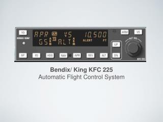
Control Signals CE Control Unit Block Diagram
Control Unit Inputs CE • Clock: control unit causes one micro-operation (or set of simultaneous micro-operations) • Instruction register: opcode of the current instruction is used to determine which micro-operations to perform during the execute cycle • Flags: needed by the control unit to determine the status of the processor and the outcome of previous ALU operations • Control signals from control bus: Provides signals to the control unit (interrupt, acknowledgement)
Control Unit Outputs CE Control signal within the processor: (type 1): cause data to be moved from one register to another. (type 2): activate ALU function. Control signals to control bus: (type 1): control signals to memory. (type 2): control signals to the I/O modules.
Control Unit and the Fetch Cycle CE • MAR <- (PC) • control unit activates the control signal that opens the gates between the bits of the PC and the bits of the MAR. • MBR <- (memory) • control signal opens gates, allowing MAR contents onto bus • memory read signal to bus • contents of data bus stored in MBR • signal to logic that increment PC and store the result back to PC
Questions • The control unit performs which 2 basic tasks? • What is sequencing and execution?
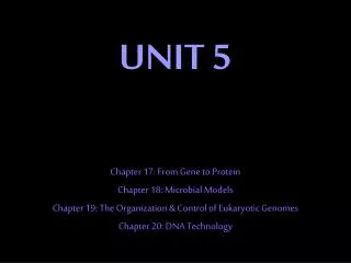
Internal Processor Organization • Usually a single internal bus • Gates control movement of data onto and off the bus • Control signals control data transfer to and from external systems bus • Temporary registers needed for proper operation of ALU CR
CPU withInternalBus NOTE: A single internal bus connects the ALU and all the processor registers CR
Internal Processor Organization • Movement of data onto and off the bus from each is register possible through gates and control signals • New registers: Y and Z • Aid in operation of ALU • Source for additional operands; temporary storage (Y input storage; Z output storage) • ALU: combinational circuit (output is a pure function of the present input only) • Control signals activate ALU function input is transformed to output (register Z is the temporary output; ALU output is NOT connected directly to BUS) CR
Intel 8085 • Other components in this processor: • Incrementer/decrementer address latch avoids use of ALU for incrementing SP or PC • Interrupt control handles interrupt signals • Serial I/O control interfaces to devices CR
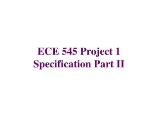
Intel 8085 Pin Configuration External signals into and out of the 8085 are linked to the external system bus. These signals interface the processor and the rest of the system. CR
External Signals • Address and Data Signals • High Address (A15-A8) • Address/Data (AD7-AD0) • Serial Input Data (SID) • Serial Output Data (SOD) • Timing and Control Signals • CLK (OUT) • X1, X2 • Address Latch Enable (ALE) • Status (S0, S1) • IO/M • Read Control (RD) • Write Control (WR) • Memory and I/O Initiated Symbols • Hold • Held Acknowledge (HOLDA) • READY • Interrupt-Related Signals • TRAP • Interrupt Request (INTR) • Interrupt Acknowledge • CPU Initialization • RESET IN • REST OUT • Voltage and Ground CR
8085 Timing • The timing of processor operations is synchronized by the clock and controlled by the control unit with control signals. • Timing diagram shows the value of external control signals. Three machine cycles (3-5 states per machine cycle) are shown. • The Address Latch Enable (ALE) signals the start of each machine cycle from the control unit. • Must give enough time for signal level to stabilize. CR
Questions • What are the temporary registers which aid in ALU operation? • What controls data transfer to and from external bus?
First Programmable Computer • Z1 began development in 1936 by Germany’s Konrad Zuse • Considered the first electrical binary programmable computer • 64-word memory (each word contained 22 bits), a total of 176 bytes memory and a clock speed of 1 Hz • Program through punch tape/output through punch tape YB
Beginning of Binary Operations • George Boole wanting a rapid development in electrical technology discovered logic functions • At that time all operations were done by opening and closing a switch • He realized that a combination of switches can bring out a new world of logical operations which he called binary logic • Boole also arrived to Boolean Algebra to solve this operations YB
Hardwired Implementation (1) • Control Unit Key Inputs are: instruction register, the clock, flags, and control bus signal • Flags and control bus are directly useful to the CU • Each bit means something • Instruction register • Provides Op-code’s that the CU uses for instructions for actions • CU logic simplified by decoder which takes an encode signal and produces a single output YB
Hardwired Implementation (2) • Clock • Repetitive sequence of pulses • Useful for measuring duration of micro-ops • Must be long enough to allow signal propagation • Different control signals at different times within instruction cycle • Need a counter with different control signals for t1, t2 etc. YB
Control Unit Logic • Processor’s use Boolean equations to define the control unit • Control Unit controls the state of instruction cycle • Controls the timing generator to reset at the end of each subcycle • Subcycle • Fetch • Indirect • Execute • Interrupt YB
Example of Boolean Equations • Consider the following interpretation • PQ = 00 Fetch Cycle • PQ = 01 Indirect Cycle • PQ = 10 Execute Cycle • PQ = 11 Interrupt Cycle Then if this expression defines C5: • C5 = P*Q*T2 + P*q*T2 • This means that the control signal C5 will be asserted during the second time unit of both the fetch and indirect cycles YB