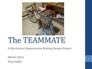
The TEAMMATE
The TEAMMATE. A Mechanical Regenerative Braking Design Project Winter 2013 Team Eight . The Team. John El- Tawil Colin MacKenzie Michael Matthews Alan Robinson. Dr. Marek Kujath. Supervisor. Outline. Introduction Design Testing Design Requirements Budget

The TEAMMATE
E N D
Presentation Transcript
The TEAMMATE A Mechanical Regenerative Braking Design Project Winter 2013 Team Eight
The Team • John El-Tawil • Colin MacKenzie • Michael Matthews • Alan Robinson • Dr. MarekKujath Supervisor
Outline • Introduction • Design • Testing • Design Requirements • Budget • Summary & Recommendations
Scope • Design/build a mechanical regenerative braking system • Capture energy dissipated during braking of a bicycle • Lower input energy to accelerate from stop • Improve rider efficiency
The Spring • System uses a spiral torsional spring • Issue: Input is CW Output is CCW • Solution: Charge outside Release inside Figure 1 – Spiral Torsional Spring
How the Spring will Work 1. 2. 3. 4. Figure 2 – Spring Dynamics
Custom Axle Figure 3 – Standard Hub (Shimano, 2013) Figure 4 - Custom Hub
Custom Axle Figure 5 – Custom Axle
The System Figure 6 – The System
Input Shaft Figure 7 – The Input Shaft
The System Figure 8 – The System
Output Shaft Figure 9 – The Output Shaft
Manual Control / Operation Figure 10 – The Manual Control Triggers
Testing • Friction losses from system • Weight losses from the system • Energy gained from the spring Figure 11 – Testing
Test # 1: Friction Losses • Energy could be lost in the system from bearing friction • A speed test was run 5 times with chains attached and detached • Final speeds were averaged and compared to determine if there were losses in energy
Friction Losses Table 1 – Average speed with system not chained Table 2 – Average speed with system chained
Friction Losses Assuming no losses from friction, the final velocities should be the same = 97.2% Losses were minimal with system engaged Therefore friction losses neglected in energy balance
Test # 2: Weight Losses • Energy lost due to added weight of the system(8.98 kg) • Accelerating a mass requires energy • The difference in accelerating the bicycle with and without the system will show the energy taken to accelerate just the system from rest.
Weight Losses Table 3 – Distance and time for acceleration with system Table 4 – Distance and time for acceleration without system
Weight Losses • extra needed to accelerate the system mass after each stop
Test # 3: Energy Gained • Spring ‘’ obtained through testing using torque sensor ratchet () • Rotational angle for a max charge, 270 degrees • Spring’s K and max lower than ideal • Limits system benefits
Testing Results • Rider uses 16.1 J less than they would without the system per acceleration • The total savings will increase based frequency of use • 34 KJ saved per semester for one team member.
Testing Summary • Showed overall net gain in energy while using the “TeamMate” • Energy gain is very low, but can be improved with two simple design improvements: • Reduce system weight (cast iron and steel not required) • Custom torsional spring (higher K and greater • The output chain can slip in high torque situations
Future Recommendations 4. Different bicycle 5. Custom back rack 6. Better bearings 1. Custom torsional spring 2. Reduce weight 3. Add output tensioner
Acknowledgements • Angus • Albert, Mark • Dr. MarekKujath • Dr. Ted Hubbard, Dr. Clifton Johnston • Ideal Bikes • Cyclesmith • Master Auto • Supermileage Team • Dr. Robert Bauer
Questions? Website: http://poisson.me.dal.ca/~dp_12_08/ Twitter: @MechTeamEight
Key Ring Key Ring
Assume is based on air resistance at and (1.022 ) NOTE: 5.63 N was increased to 10 N to compensate for relative wind velocity and neglected mechanical losses in bicycle. (9) (10) = 44.0 Nm (11) NOTE: It was later determined through testing that the maximum torque required was approximately 35.0 Nm but to maintain a conservative approach, all following calculations are based on 44.0 Nm.
Safety Factor of Bicycle Chain S.F. = = 1.78
Safety Factor of Disc Brake Safety Factor
Safety Factor of Spiral Torsional Spring Safety Factor
Safety Factor of Shafts Subjected To Torsion Safety Factor
Safety Factor of Shafts Subjected to Shear Safety Factor
Test # 4: Energy Storage System Efficiency • Compare input and output speeds on the stand • With and without torque resistance