Download

1 / 41
410 likes | 552 Vues
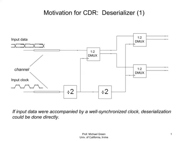
EECS 219B Spring 2001. Timing Analysis I Andreas Kuehlmann. Timing Analysis - Delay Models. Simple model 1:. Ak. D k. A3. A1. A2. A k = arrival time = max( A 1 ,A 2 ,A 3 ) + D k D k is the delay at node k , parameterized according to function f k and fanout node k

E N D
EECS 219BSpring 2001 Timing Analysis I Andreas Kuehlmann
Timing Analysis - Delay Models • Simple model 1: Ak Dk A3 A1 A2 Ak = arrival time = max(A1,A2,A3) + Dk Dkis the delay at node k, parameterized according to function fk and fanout node k • Simple model 2: Ak Ak = max{A1+Dk1, A2+Dk2,A3+Dk3} 0 Ak Dk3 Dk1 Dk2 A3 A1 A3 A1 A2 A2 • Can also have different times for rise time and fall time
Static delay analysis // level of PI nodes initialized to 0, // the others are set to -1. // Invoke LEVEL from PO Algorithm LEVEL(k) { // levelize nodes if( k.level != -1) return(k.level) else k.level = 1+max{LEVEL(ki)|ki fanin(k)} return(k.level) } // Compute arrival times: // Given arrival times on PI’s Algorithm ARRIVAL() { for L = 0 to MAXLEVEL for {k|k.level = L} Ak = MAX{Aki} + Dk }
Required Times Sk Sj Required times: given required times on primary outputs • Traverse in reverse topological order (i.e. from primary outputs to primary inputs) • if (ki , k ) is an edge between ki and k, Rki ,k = Rk - Dk (this is the edge required time) • Hence, the required time of output of node k is Rk = min ( Rk,kj| kj fanout(k) ) k j Ski ki ki
Propagating Slacks Slacks: slack at the output node k is Sk = Rk-Ak Since Rki,k=Rk-Dk Ski,k =Rki,k - Aki Ski,k + Aki = Rk-Dk = Sk + Ak - Dk Since Ak = max {Akj } + Dk Ski,k = Sk + max {Akj } - Aki kj , ki fanin (k ) Ski = min{Ski,j} j fanout (ki ) Notes: • each edge is the graph has a slack and a required time • Negative slack is bad. Sk Sj k j Ski ki ki
Sequential networks • Arrival times known at l1 and l2 • Required times known at l3, l4, and l5 • Delay analysis gives arrival and required times (hence slacks) for C1, C2, C3, C4 C2 C1 l4 l1 C3 C4 l2 l3 l5
Sequential Networks Note: Latch l5 may be transparent • t1 is the beginning of latch transparent time • Arrival time at l5 output = max { arrival time at l5 input, t1 } + Dlatch(hold) • Required time at l5 input = min { required time at l5 output, t2 } - Dlatch(set_up) C2 C1 l4 l1 C3 C4 l2 l3 l5 clock t1 t2
Static critical paths Min-Max problem: minimize max{-Si , 0} A static critical path of a Boolean network is a path P = {i1,i2,…,ip } where Sik, ik+1 < 0 Note: if a node k is on a static critical path, then at least one of the fanin edges of k is critical. Hence, all critical paths reach from an input to an output. Note: There may be several critical paths
Example: Static critical paths A1=6 R1=5 A2=5 R2=5 S1=-1 R3=3 S2=0 R7=1 S3,1=-1 R9=-1 S4,1 = -1 S4,2 = 0 S5,2 = 1 S6,3 = 0 S7,3 = -1 S7,4 = -1 S7,5 = 1 S8,6 = 0 S9,7 = -1 critical path edges R1=5 R2=5 -1 6 5 0 2 1 2 1 1 -1 4 4 3 -1 0 2 2 1 3 4 5 -1 -1 0 1 1 2 1 2 6 7 0 -1 9 8 A9=0 A8=0 Ski,k = Sk + max{Akj } - Aki , kj,ki fanin(k) Sk = min{Sk,kj }, kj fanout(k)
Timing analysis problems We want to determine the true critical paths of a circuit in order to: • determine the minimum cycle time that the circuit will function • identify critical paths for performance optimization - don’t want to try to optimize the wrong (non-critical) paths Implications: • Don’t want false paths (produced by static delay analysis) • Delay model is worst case model. Need to ensure correctness for case where ith gate delay DiM
Functional Timing Analysis What is Timing Analysis? Estimate when the output of a given circuit gets stable 0 Combinational block 0 0 T clock
Why Timing Analysis? Timing verification • Verifies whether a design meets a given timing constraint • Example: cycle-time constraint Timing optimization • Needs to identify critical portion of a design for further optimization • Critical path identification In both applications, the more accurate, the better
Timing Analysis - Basics Naïve approach - Simulate all input vectors with SPICE • Accurate, but too expensive Gate-level timing analysis Focus of this lecture • Less accurate than SPICE due to the level of abstraction, but much more efficient • Scenario: • Gate/wire delays are pre-characterized (accuracy loss) • Perform timing analysis of a gate-level circuit assuming the gate/wire delays
1 1 Gate-level Timing Analysis False path aware arr(z)? A naive approach is topological analysis • Easy longest-path problem • Linear in the size of a network Not all paths can propagate signal events • False paths • If all longest paths are false, topological analysis gives delay overestimate Functional timing analysis = false-path-aware timing analysis • Compute false-path-aware arrival time z x1 x2 arr(x1)=0 arr(x2)=0
Example: 2-bit Carry-skip Adder s0 c_in Length 1 Length 5 a0 s1 b0 1 0 c_out a1 b1 mux ripple carry adder
False Path Analysis - Basics Is a path responsible for delay? • If the answer is no, can ignore the path for delay computation Check the falsity of long paths until we find the longest true path • How can we determine whether a path is false? Delay underestimation is unacceptable • Can lead to overlooking a timing violation Delay overestimation is not desirable, but acceptable • Topological analysis can give overestimate, but never give underestimate
Controlled value of AND Non-Controlling value of AND Controlling value of AND Controlled value of OR 1 1 0 Controlling value of OR Non-Controlling value of OR Controlling/Non-Controlling Values 0 0 1
t=0 t=0 t=0 Static Sensitization A path is statically-sensitizable if there exists an input vector such that all the side inputs to the path are set to non-controlling values • This is independent of gate delays Controlling value! 1 0 These paths arenot statically-sensitizable 1 0 The longest true path is of length 2?
0 0 Static Sensitization • The (dashed) path is responsible for delay! • Delay underestimation by static sensitization (delay = 2 when true delay = 3) • incorrect condition 1 2 3 1 2 1 0
What is Wrong with Static Sensitization? The idea of forcing non-controlling values to side inputs is okay, but timing was ignored • The same signal can have a controlling value at one time and a non-controlling value at another time. How about timing simulation as a correct method?
2 2 2 3 1 1 1 1 4 4 Timing Simulation 0 0 Implies that delay = 0 for these inputs BUT!
2 0 2 3 1 0 2 Timing Simulation 2 1 1 4 3 1 4->2 Implies that delay = 4 with the same set of inputs.
What is Wrong with Timing Simulation? If gate delays are reduced, delay estimates can increase Not acceptable since • Gate delays are just upper-bounds, actual delay is in [0, d] • Delay uncertainty due to manufacturing • We are implicitly analyzing a family of circuits where gate delays are within the upper-bounds
Monotone Speedup Property Definition: For any circuit C, if • C’ is obtained from C by reducing some gate delays, and • delay_estimate(C’) delay_estimate(C), then delay_estimate has Monotone Speedupproperty Timing simulation does not have this property
2 0 2 3 1 1 4 1 1 4 0 4 Timing Simulation Revisited means that the rising signal occurs anywhere between t = -infinity and t = 4. 4 X-valued simulation
Timing Simulation Revisited Timed 3-valued (0,1,X) simulation • called X-valued simulation Monotone speedup property is satisfied. Underlying model of • floating mode condition [Chen, Du] • Applies to “simple gate” networks only • viability[McGeer, Brayton] • Applies to general Boolean networks
For finalcontrolledoutput value 0 late 0 Earliest-arriving controlling value determines the output stable time early 1 For finalnon-controlled output value 1 early 1 Latest-arriving non-controlling value determines the output stable time late 1 Floating Mode Analysis Assume that all nodes have X before applying an input vector • conservative assumption Path sensitization (floating-mode - for simple gate networks only)
False Path Analysis Algorithms Checking the falsity of every path explicitly is too expensive - exponential # of paths State-of-the-art approach: • Start: set L = Ltop /2= topological longest path delay /2 Lold = 0 • Binary search: If (Delay(L)) (*) dL = |L-Lold|/2, Lold = L, L = L + dL Else, dL = |L-Lold|/2, Lold = L, L = L - dL If (L > Ltop or dL < threshold), L = Lold , done (*)Delay(L) = 1 if there an input vector under which an output gets stable only at time t where L t ?Can be reduced to • a SAT problem [McGeer, Saldanha, Brayton, ASV] or • a timed-ATPG [Devadas, Keutzer, Malik]
SAT-based False Path Analysis Decision problem: Is there an input vector under which the output gets stable only after t = T ? Idea: • characterize the set of all input vectors S(T) that make the output stable no later than t = T • check if S(T) contains S = all possible input vectors This check is solved as a SAT problem: Is S \ S(T) empty? - set difference + emptiness check • Let F and F(T) be the characteristic functions of S and S(T) • Is F !F(T) satisfiable?
Example d g a b e f c Assume all the PIs arrive at t = 0, all gate delays = 1 Is the output stable time t > 2?
d g a b e f c Example g(1,t=2) : the set of input vectors under which g gets stable to value = 1 no later than t =2 Onset: stabilized by t=2? g(1,t=2) = d(1,t=1) Ç f(1,t=1) = (a(0,t=0) Ç b(0,t=0)) Ç (c(1,t=0) È e(1,t=0)) = !a!b(c È Æ) = !a!bc = S1(t=2) g(1,t=¥) = onset = !a!bc = g(1,t=2) = S1
d g a b e f c Example g(0,t=2) : the set of input vectors under which g gets stable to value = 0 no later than t=2 g(0,t=2) = d(0,t=1) È f(0,t=1) = (a(1,t=0) È b(1,t=0)) È (c(0,t=0) Ç e(0,t=0)) = (a+b) + (!c Ç Æ) = a+b = S0(t=2) g(0,t=¥) = offset = a+b+!c = S0
d g a b e f c Example g(0,t=2) : the set of input vectors under which g gets stable to 0 no later than t=2 Offset: NOTstabilized by t=2 under abc=000 g(0,t=2) = a+b g(0,t=¥) = offset = a+b+!c g(0,t=¥) \ g(0,t=2) = (a+b+!c) !(a+b) = !a !b !c = satisfiable
For general networks Can build a companion network to represent each output: output(0,t=T’) or output(1,t=T’) Take each gate g from outputs in reverse topological order. For g(1,t=T): • Compute all primes of gate onset • Make AND gate for each prime • OR these together to form g(1,t=T) For g(0,t=T), do same but for offset For inputs to these primes, form companion networks for {fi(1,t = T-Dg), fi(0,t = T-Dg), i in FI(g)} fi(1,T-Dg) p1 Now form SAT clauses for this network and solve g(1,T) p2 + fj(0,T-Dg) p3
Summary False-path-aware arrival time analysis is well-understood • Practical algorithms exist • Can handle industrial circuits easily Remaining problems • Incremental analysis (make it so that a small change in the circuit does not make the analysis start all over) • Integration with logic optimization • DSM issues such as cross-talk-aware false path analysis
Timed ATPG Yet another way to solve the same decision problem A generalization of regular ATPG: • regular ATPG • find an input vector that differentiates a fault-free circuit and a faulty circuit in terms of functionality • Timed ATPG • find an input vector that exhibits a given timed behavior • Timed extension of PODEM
(X,[0,0]) (X,[0,0]) (X,[0,0]) Timed ATPG (0,[3,3])
Timed ATPG (X,[1,1]) (0,[3,3]) (0,[0,0]) (X,[2,3]) (0,[1,1]) (X,[0,0]) (X,[1,2]) (X,[0,0])
(0,[3,3]) (0,[0,0]) (0,[0,0]) (X,[0,0]) Timed ATPG (1,[1,1]) (X,[2,3]) (0,[1,1]) (X,[1,2])
(0,[3,3]) (0,[0,0]) (0,[0,0]) (1,[0,0]) Timed ATPG (1,[1,1]) (1,[2,2]) (0,[1,1]) (1,[1,1]) Value and time conflict! Backtrack!
(0,[3,3]) (0,[0,0]) (0,[0,0]) (0,[0,0]) Timed ATPG (1,[1,1]) (0,[3,3]) (0,[1,1]) Justified! (0,[2,2]) Found an input vector that makes the output stable to 0 no earlier than t=3