Download

1 / 19
200 likes | 693 Vues
ME421 Heat Exchanger and Steam Generator Design. Lecture Notes 6 Double-Pipe Heat Exchangers. Introduction. Introduction. DP HEX: one pipe placed concentrically inside another One fluid flows through inner pipe, the other through the annulus Outer pipe is sometimes called the shell

E N D
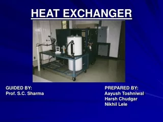
ME421Heat Exchanger andSteam Generator Design Lecture Notes 6 Double-Pipe Heat Exchangers
Introduction • DP HEX: one pipe placed concentrically inside another • One fluid flows through inner pipe, the other through the annulus • Outer pipe is sometimes called the shell • Inner pipe connected by U-shaped return bends enclosed in a return-bend housing to make up a hairpin, so DP HEX = hairpin HEX • Hairpins are based on modular principles: they can be arranged in series, parallel, or series-parallel combinations to meet pressure drop and MTD requirements; add-remove as necessary
Usage Areas / Advantages • Sensible heating / cooling, small HT areas (up to 50 m2) • High pressure fluids, due to small tube diameters • Suitable for gas / viscous liquid (small volume fluids) • Suitable for severe fouling conditions (easy to clean and maintain) • Finned tubes can be used to increase HT surface per unit length, thus reduce length and Nhp • Outside-finned inner tubes most efficient when low h fluid (oil or gas) flows through annulus • Multiple tubes can be used inside the shell • Used as counterflow HEX, so they can be used as an alternative to shell-and-tube HEX
Thermal / Hydraulic Design Inner Tube • Use correlations to find HT coefficient and friction factor • Total pressure drop Annulus • Same procedure as above, but use • Hydraulic diameter, Dh = 4Ac/Pw for Re calculation • Equivalent diameter, De = 4Ac/Ph for Nu calculation • For a hairpin HEX with Bare Inner Tube, • Dh = Di - do • De = (Di2 - do2)/do Study Example 6.1 (detailed analysis)
Thermal / Hydraulic Design (continued) • For a hairpin HEX with Multitube Longitudinal Finned Inner Tubes • Get Dh and De using • Unfinned, finned, and total outside HT surface areas
Thermal / Hydraulic Design (continued) • Overall HT coefficient based on outer area of inner tubes where is the overall surface efficiency Area ratios At/Ai and Af/At are needed Rw is for bare tube wall hf is the efficiency of a rectangular continuous longitudinal fin (for other types of fins, use references) * h affects fin efficiency; have the fluid with the poorest HT properties on the finned side
Thermal / Hydraulic Design (continued) • The heat transfer equation is (heat duty equation) • The design problem, in general, includes determining the total outer surface area of the inner tubes from the above equation. • If the length of hairpins is fixed, then Nhp can be calculated. • U can also be based on the inner area of the inner tubes, Ai • For counterflow and parallel flow arrangements, no correction is necessary for Tm. However, if hairpins are arranged in series/parallel, a correction must be made (later). • Study Example 6.2 (detailed analysis)
Parallel / Series Arrangement of Hairpins • If the design indicates large Nhp, it may not be practical to connect them all in series for pure counterflow. A large quantity of fluid through pipes may result in p > pallowable • Solution: Separate mass flow into parallel streams, then connect smaller mass flow rate side in series. This is a parallel-series arrangement. • If such a combination is used, the temperature difference of the inner pipe fluid will be different for each hairpin. • Thus, in each hairpin section, different amounts of heat will be transferred and true mean temperature difference, Tm will be different from the LMTD.
The true mean temperature difference in becomes dimensionless quantity S is • For n hairpins, S depends on the number of hot-cold streams and their series-parallel arrangement. • Simplest case is to either divide the cold fluid equally between n hairpins in parallel or to divide the hot fluid equally between n hairpins in parallel.
For one-series hot fluid and n1-parallel cold streams, • For one-series cold fluid and n2-parallel hot streams, • Then, the total heat transfer rate is
In the previous equations, it is assumed that U and cp of the fluids are constant, and the heat transfer rates of the two units are equal. • Graphs are available in literature for LMTD correction factor F as well. • If number of tube-side parallel paths is equal to the number of shell-side parallel paths, regular LMTD should be used.
Total Pressure Drop • Total pressure drop includes frictional pressure drop, entrance and exit pressure drops, static-head, and the momentum-change pressure drop. • Frictional pressure drop is • For frictional pressure drop, use correlations from Chapter 4 or Moody diagram. Add equivalent length of the U-bend to the L in tube-side (Dh = di) pressure drop. • You may need to account for the effect of property variations on friction factor.
Total Pressure Drop (continued) • Entrance and exit pressure drops through inlet and outlet nozzles is evaluated from where Kc = 1.0 at the inlet and 0.5 at the outlet nozzle. • Static head is pf = H, where H is the elevation difference between inlet and outlet nozzles. • For fully developed conditions, momentum-change pressure drop is • In all pressure drop calculations for design, allowable p must be considered. • Cut-and-twist technique increases h in longitudinal finned-tube HEX. See book for p details.
Design and Operational Features • In hairpin HEX, two double pipes are joined at one end by a U-tube bend welded to the inner pipes, and a return bend housing on the shell-side. The housing has a removable cover to allow removal of inner tubes. • Double-pipe HEX have four key design components • shell nozzles • tube nozzles • return-bend housing and cover plate on U-bend side • shell-to-tube closure on other side of hairpin(s) • The longitudinal fins made from steel are welded onto the inner pipe. Other materials can be joined by soldering. • Multiple units can be joined by bolts and gaskets. • For low heat duty applications, simple constructions, easy assembly, lightweight elements and minimum number of parts contribute to minimizing costs.
IPS: inch per second (unit system) NFA: net flow area