Download
1 / 31
310 likes | 321 Vues
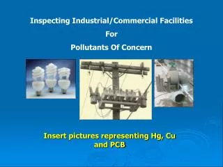
This guide outlines the essential steps for inspecting the construction of bioretention facilities, covering areas like excavation, drainage management, underdrains, and soil media mix. Ensure proper construction following the checklist.

E N D
Inspecting Construction of Bioretention Facilities Carlton Thompson and Jeff Cowling
Construction Checklist • Include the Checklist in the plans • Suggest getting the checklist on a plan sheet in the plans to give the contractor heads up about what is inspected and when. • Make clear at the pre-construction meeting the steps for inspection. • Have a separate meeting with the contractor and sub-contractors prior to starting the excavation for the bioretention facilities.
Use checksheet Similar to bldg Workcard Binder or Plans Construction Checklist
Layout • Layout (Certification may be required) • Square footage of the facility meets or exceeds minimum shown in Stormwater Control Plan. • Site grading and grade breaks are consistent with the boundaries of the tributary Drainage Management Area(s) shown in the Stormwater Control Plan. • Preliminary inlet elevation of the facility is low enough to receive drainage from the entire tributary Drainage Management Area(s). • Locations and elevations of overland flow or piping, including roof leaders, from impervious areas to the facility have been laid out and any conflicts resolved. • Rim elevation of the facility is laid out to be level all the way around, or elevations are consistent with a detailed cross-section showing location and height of interior dams. • Locations for vaults, utility boxes, and light standards have been planned so that they will not conflict with the facility. • Facility protected as needed from construction-phase runoff and sediment.
Excavation • Excavation(Certification may be required) • Excavation conducted with materials and techniques to minimize compaction of soils within the facility area. • Excavation is to proper area and depth. • Slopes or side walls protect from sloughing of native soils into the facility. • Moisture barrier, if needed, added to protect adjacent pavement or structures. • Native soils at bottom of excavation are ripped or loosened to promote infiltration.
Overflow Inlet/Surface Connection to Storm System • Overflow inlet is at specified elevation (typically no lower than two inches below facility rim). • No knockouts or side inlets are in overflow riser. • Inlet location selected to minimize surface flow velocity (near and offset from inlet recommended). • Grating selected to exclude mulch and litter (beehive or atrium-style grates with ¼" openings recommended). • Inlet is connected to storm drain via appropriately sized piping. • Facility emergency overflow path designed to avoid flood damage.
Underdrain • Underground Connection to Storm Drain/Outlet Orifice • Perforated pipe underdrain (PVC SDR 35 or approved equivalent) is installed with holes facing down. • No filter fabric is installed around the underdrain. • Perforated pipe is connected to storm drain (treatment-only) or orifice (treatment-plus-flow-control) per plans. • Underdrain pipe is at elevation shown in plans. In facilities allowing infiltration, preferred elevation is above native soil (but low enough to be covered at least 2 inches by Class 2 perm); in sealed planter boxes or bioretention facilities with liners, preferred elevation is as near bottom as possible. • Cleanouts are in accessible location(s) and connected via sweeps. • Structures (arches or large diameter pipes) for additional subsurface storage are installed as shown in plans and specifications and have the specified volume.
Drain Rock (12” Layer) • Rock is installed as specified. Class 2 permeable, Caltrans specification 68-1.025 recommended, OR 4"-6" pea gravel is installed at the top of the crushed rock layer. • Rock is smoothed to a consistent top elevation. Depth and top elevation are as shown in plans, accounting for depth of soil mix and mulch to follow and required top reservoir depth. • No filter fabric is placed between the subdrain and soil mix layers.
Soil Media Mix • Soil media mix is as specified. Quality of mix is confirmed by delivery ticket or on-site testing as appropriate to the size and complexity of the job. • Mix is installed in lifts not exceeding 12". • Mix is not compacted during installation but may be wetted thoroughly to encourage consolidation. • Mix is smoothed to a consistent top elevation. Depth of mix (18" minimum) and top elevation are as shown in plans, accounting for depth of mulch to follow and required top reservoir depth.
Irrigation • Irrigation system is installed so it can be controlled separately from other landscaped areas. Smart irrigation controllers and drip emitters are recommended. • Spray heads, if any, are positioned to avoid direct spray into outlet structures.
Planting • Plants are installed consistent with the approved planting plan. • Any trees and large shrubs are staked securely. • No fertilizer is added. Compost tea may be used. • No native soil or clayey material are imported into the facility with plantings. • 1" to 2" mulch may be applied following planting. Mulch selected to avoid floating. • Maintain final design elevation of soil mix following planting. • Curb openings are free of obstructions.
Final Engineering Inspection • Drainage Management Area(s) are free of construction sediment; landscaped areas are stabilized. • Inlets are installed to provide smooth entry of runoff from adjoining pavement, have sufficient reveal (drop) from the adjoining pavement to the top of the mulch or soil mix, and are not blocked. • Inflows from roof leaders and pipes are connected and operable.
Final Engineering Inspection (Cont’d) • Temporary flow diversions are removed. • Rock or other energy dissipation at piped or surface inlets is adequate. • Overflow outlets are configured to allow the facility to flood and fill to near rim before overflow. • Plantings are healthy and becoming established. • Irrigation is operable. • Facility drains rapidly; no surface ponding is evident. • Any accumulated construction debris, trash, or sediment is removed from facility.
Bullet 1 Bullet 2 Bioretention during storm
City Hall Downspout Bioretention Area