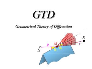
GTD
GTD. Geometric Tolerances and Dimensions. Why Geometric Tolerances and Dimensioning. To ensure interchangeability of mating parts during assembly To eliminate controversy and guesswork when drawing is interpreted

GTD
E N D
Presentation Transcript
GTD Geometric Tolerances and Dimensions
Why Geometric Tolerances and Dimensioning • To ensure interchangeability of mating parts during assembly • To eliminate controversy and guesswork when drawing is interpreted • To ensure the drawing reflects the form and function requirements of the manufactured parts
Principles of datum specification Three perfect plans used to locate an imperfect part. • Three point contact is used on the primary plane. b. Two point contact is used on the secondary plane. c. One point contact is used on the tertiary plane
Symbols Advantages: 1. The symbol has uniform meaning. 2. Symbols are compact, quickly drawn, and can be placed on the drawing where the control applies. 3. Symbols are the international language and surmount individual language barriers. 4. Geometric tolerance symbols follow the established precedent of other well known symbol systems, e.g., electrical and electronic, welding, surface texture.
HOLE PIN
MMC • The actual local size of the hole at. 245 and the pin at Ø .240 of the figure are the Maximum material condition Ø
LMC • The actual local size of the hole at Ø .255 and the pin atØ .230 of the figure are the least material condition
TERMINOLOGY • VIRTUAL CONDITION - A constant boundary generated by the collective effects of a size feature’s specified MMC or LMC and the geometric tolerance for that material condition.
VIRTUAL CONDITION • Virtual condition, based on MMC or L M C is a feature‘s extreme boundary; it represents the “worse case” • For MMC, “worse case” concerns fits and/or clearances with mating parts For LMC, “worst case” is concerned with strength, alignment, wall thickness, etc. with reference to mating parts
VIRTUAL CONDITION (MMC- PIN) • Virtual Condition for a Pin (Based on Maximum Material Condition) = Maximum Material Condition + the Stated Position or Orientation Tolerance • VC = MMC + Tolerance
VIRTUAL CONDITION (MMC- Hole) • Virtual Condition for a Hole (Based on Maximum Material Condition) = Maximum Material Condition - the Stated Position or Orientation Tolerance • VC = MMC - Tolerance
VIRTUAL CONDITION (LMC- PIN) • Virtual Condition for a Pin (Based on Least Material Condition) = Least Material Condition - the Stated Position or Orientation Tolerance • VC = LMC - Tolerance
VIRTUAL CONDITION (LMC- Hole) • Virtual Condition for a Hole (Based on Least Material Condition) = Least Material Condition + the Stated Position or Orientation Tolerance • VC = LMC + Tolerance