Download
1 / 11
110 likes | 228 Vues
This document provides a thorough overview of the 774X DCDA check valves, detailing modification history since production began in 1998. Notably, the 2.½” model was discontinued in 2003, followed by the 6” and 8” sizes in 2006. The guide covers assembly specifications, including the check modules' size differences, removal procedures for single access covers, cam checks, and check seats, as well as the necessary tools and techniques for inspection and reassembly. Maintenance tips include lubrication and proper installation sequences for optimal performance.

E N D
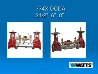
Modification Overview • Production began in 1998. • The 2 ½” 774X DCDA was discontinued in 2003. • The 6” and 8” sizes were discontinued in 2006. • All “X” assemblies use check modules that are one size smaller than the pipe size. * Example: 8” size assembly uses 6” parts
Single Access Cover Removal • Cover is secured by a grooved coupling. • Cover has no spring load.
Check Valve Removal • Check valve modules are called “Cam Checks”. • Checks are o-ring sealed and threaded into body. • #1 Check must be removed before #2 can be removed.
Check Valve Removal • Cam checks unscrew counterclockwise by hand “if possible”. *Do not use cam arm as a handle to unscrew.
Check Valve Removal • If too tight, place a drift punch or solid rod (long screwdriver) in one of the holes on the outer edge of the check module. • Tap with hammer in correct direction (counterclockwise) to loosen.
Check Valve Removal Notes • There are “special tools” available to help remove check modules.
Check Seat Removal • Check seats are part of each module and can not be removed. • If the seat is damaged, the complete check module will need to be replaced.
Check Disc Inspection 6” • The disc assembly is part of the module and can not be removed. • For inspection and cleaning, lift the cam arm and hold in open position. *Raise the clapper so that the end of the cam arm rests between the roller and clapper.
Check Disc Inspection 8” • For inspection and cleaning locate the stud on the outlet flange of the assembly. • Place the cam arm hole on the stud and open the check valve so that the cam rests between the roller and clapper.
Check Valve Reassembly Notes • Change and lubricate check o-ring. • Install #2 check first then #1 check. • # 2 check should be tightened with a long screwdriver. • Tighten #1 check firmly by hand only. • Lubricate the outside edge of the groove coupler gasket.