Wave-Particle Interaction
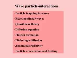
Wave-Particle Interaction. Waves: Importance of waves MHD waves, Plasma waves Wave-particle interaction: resonance condition pitch-angle diffusion Radiation belt remediation. Waves in Space. MHD waves: frequencies much below ion gyrofrequency

Wave-Particle Interaction
E N D
Presentation Transcript
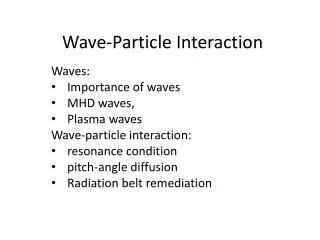
Wave-Particle Interaction Waves: Importance of waves MHD waves, Plasma waves Wave-particle interaction: resonance condition pitch-angle diffusion Radiation belt remediation
Waves in Space • MHD waves: • frequencies much below ion gyrofrequency • MHD modes: Alfven mode, slow and fast modes, entropy mode • PC waves: (ULF waves) • PC 1 (0.2-5 sec): ~ 1sec, ion cyclotron waves near the subsolar magnetopause • PC 3 (10-45sec)-4 (45-150 sec): ~ 1 min, waves generated in the magnetosheath and field resonance along the field in the inner magnetosphere or radial to the field • PC 4-5 (150-600 sec): ~3-20 min, outer magnetospheric field-aligned resonance • Pi waves: • Pi 1 (1-40 sec) • Pi2 (40-150 sec): irregular, associated with substorms • Measured with magnetometers/electric probes in time series, the Fourier analysis • Mode identifiers: Compressional vs. transverse
Waves in Space, cont. Plasma waves: (VLF and ELF waves) Frequencies above the ion cyclotron frequency Measured by radio receivers with antennas (electric dipole for E-field, search coil for B-field) Mode identifier: electrostatic vs. electromagnetic Electrostatic: dB=0, dE along k or k =0 EM modes: dE/dB ~ Vphase Modes: Ion cyclotron Whistlers (hiss, chorus, loin roar) Electron cyclotron, and harmonics Plasma frequency Above plasma frequency Odd-half electron gyro harmonics
Structure of the Magnetopause Northward IMF Southward IMF
Plasma Waves at the MagnetopauseNorthward IMF Southward IMF
The wave environment in space Meredith et al [2004]
plasmaspheric hiss Equatorial distribution of waves Sun • Wave power distribution: W(L, MLT, lat, f, y, f, M, D, t) • L: L-shell • MLT: Magnetic Local Time • Lat: geomagnetic latitude • f: wave frequency • y: wave normal angle, zenith • f: wave normal angle, azimuth • M: ULF, EMIC, magnetosonic, hiss, chorus, whistlers, ECH, … ) • D: Duty cycle, i.e., % of actual occurrence • t: Storm/substorm phase? • LANL wave database (Reiner Friedel) • NASA VWO (Shing Fung); Also ViRBO for particle data ULF EMIC waves Chorus magnetosonic waves Meredith et al. 2008 GEM tutorial
Plasma Waves and Their Possible Sources ULF waves Shawhan [1985]
Wave Properties • Frequency: ω=2π/f • Wavevector: k • Dispersion relation: ω=(k) • CMA diagram: (in radio science: no ion effects) • ω ~ k diagrams • Phase velocity: Vphase = ω/k • Group velocity: • Wave packet: dω/dk • Single wave (dω =0!): dω/dk0
Dispersion Relations Co=Cutoff: n=c/Vphase=k=0
MHD Dispersion Relations and Group Velocities (Friedrichs diagram) For Alfven mode: Note that in this expression kx and ky do not need to be 0 but they do not contribute to Vg (but may reduce it). The following physical process explains that the energy propagates along B at a speed of VA , as shown in the figure, and kx and ky both contribute to the energy flux.
Physical picture of signal of point source propagating in anisotropic medium • Signal front S-t1=>S-t2 • Phase front W: k1-t1=>k1-t2; k2-t1=>k2-t2 • Group front (most energy) G1=>G2 • Signals in k1 and k2 are in phase only along kg • Signals in other regions cancel • Phase along kg: where vg = r/t: ray velocity • Waves propagate in all directions (not a beam) • Net amplitude is seeing only within a narrow angle
Wave Analyses • Amplitude (power): as function of time or location (plasma conditions) • Propagation direction: k: minimum variance dB perpendicular to k • Polarization: linear, circular • Source region? • local plasma conditions unstable to instabilities at the observed frequency range, • particle energy becomes wave energy • Free energy that generates a wave comes from non-Maxwellian part of the distribution (hot population, beams, anisotropy) • Dispersion relation is not relevant • Propagation region? • instability conditions not relevant, unless the mode is strongly damped • Dispersion relation is satisfied • Dispersion relation is (often) determined by the bulk (cold) population • Absorption frequency: • particles gain energy from waves through resonance • Manmade source: active transmission • Above the ionosphere: GPS, communication s/c, TV s/c, f >fpe: refraction. • Above the ionosphere: RPI, ISIS, f~fpe: refraction, reflection • Above the ionosphere: DSX, whistler: field-aligned propagation • Below the ionosphere: VLF radars, beacons, f<fpe: waveguide propagation • Below the ionosphere: digisondes, f~fpe: refraction, reflection
Resonance Condition • Particle motion: Particle motion can be decomposed to • Plasma oscillation: ωpe, ωpi • Gyro motion: ωce, ωci • Field-aligned motion: V|| • Guiding center drift motion (perpendicular to B): VD • Doppler shift ω = ω0+kV • The frequency a particle seen a wave frequency ω0in its own frame of reference is Doppler shifted frequency, ω • In general, when not in resonance, wave field randomly accelerates and decelerates the particle • Resonance condition • ω = nωce, nωci, nωpe, nωpi; n = 0, 1, 2, … • Landau damping: n =0 • Dominant modes: n = 1
Wave-particle Resonance Interaction • In resonance, the wave field is in phase with the particle motion and will either periodically (or constantly) accelerate or decelerate the particle • When wave field accelerates (decelerates) the particle, the particle gains (loses) energy and the wave is damped (grows) • Pitch angle diffusion: whistler mode resonates with V|| • Drift mode resonance: MHD mode resonates with VD • Out of tune: when a resonating particle travel along a field, (B changes) the Doppler-shifted frequency may become out of tune from the resonance condition
Pitch-Angle Diffusion • Pitch angle: tan =V/V|| • Pitch angle change by a wave • Electrostatic wave (k||dE, or k=0: not propagating) • dE along B • dE perpendicular to B • EM wave (kdB) • Linear dB • Circular dB • Magnetic field cannot do work (in the particle frame of reference where resonance occurs) • For a resonance particle, it loses or gains energy in the plasma frame • Pitch angle change: d|VxdB| • Pitch angle diffusion: • Particles may have equal chances to gain or lose energy as the phases of gyration and the wave are random • Pitch angle Diffusion: if there is a loss-cone in the distribution function and the particles that are scattered into the loss-cone will be lost to the atmosphere.
Pitch Angle Scattering (quasi-linear theory) • Parallel acceleration by wave magnetic field • Pitch-angle scattering • Pitch-angle diffusion coefficient
Resonance Time and Total Diffusion • Resonance condition • Shift from resonance • In-tune condition • In-tune length • Diffusion Coefficient • Total angular diffusion
Radiation Belt Remediation • Lifetime of radiation belt particles are very long, in particular electrons • Objective: Mitigate threats to low-earth orbit satellites (LEO) from energetic electrons by shortening their lifetime. • Energy range: 0.5~2.5 MeV • L-range: 1.7~3.5 • Approach: pitch-angle scattering by whistler mode waves Abel and Thorne, 1998 Precipitation lifetime (days) L-shell
NLK-Washington 24.8 kHz Dynamic Spectra Measured from IMAGE/RPI Passive mode
Observations of NML station, 2001/2002 La Moure, ND, L=3.26, 500 kW
Signal amplitude vs. station-footprint distance 10dB/1000km Signal amplitude, dB Distance, km DHO
VLF power in space from ground-based transmitters • Peak electric field amplitude: 100 V/m • Assuming whistler wave phase velocity: ~ 0.1 c • Magnetic field amplitude at foot: 2×10-11 T (20 pT) • Poynting Flux: 510-9 W/m2 • Total flux: ~ 50 kW out of 500 kW • Ionospheric coupling factor < 10% • No evidence for wave trapping/amplification in low L-shells • Requires 1 MW transmitter
Manmade Whistler Waves: Space-borne Transmitters • Questions to address: • Orbit • Frequency • Power • Space-borne transmitter: • Equatorial orbit: +: long wave-particle interaction time –: low transmission efficiency, (plasma conditions) –: large spatial area, more power needed –: more expensive, • Low-orbit: +: high transmission efficiency- (high frequencies) +: target only 10% of harmful population (energy selective) =>low power, small spatial area, +: low launch costs –: shorter wave-particle interaction time
1 2 3 4
LORERS Scenario • Low-altitude (~3000 km) high-inclination (~50°) orbit flying above LEOs (~1000 km) across feet of flux tubes of radiation belt. • Tune to frequencies to clean 0.5~2.5 MeV electrons with pitch angles that have mirror points below 1500 km. • As a result of natural pitch angle diffusion, the lowest mirror point continues to move down from 1500 km after cleaning • Revisit the same region before the lowest mirror point reaches 1000 km due to natural pitch angle diffusion • Re-clean 0~1500 km. • Natural diffusion is the main diffusion mechanism. • LORERS only helps to speed up the diffusion process at the feet of the field lines, which is less than 10 % of the total population.