Download
1 / 58
640 likes | 919 Vues
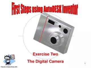
First Steps using AutoDESK Inventor. Exercise Two The Digital Camera. Fastedd @ Helpful Notes 2004. Get to Know your Mouse. Select in the tutorial means using the left mouse button. The Esc key on your keyboard is used to cancel a command. Right mouse button

E N D
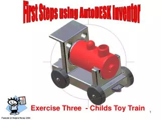
First Steps using AutoDESK Inventor Exercise Two The Digital Camera Fastedd @ Helpful Notes 2004
Get to Know your Mouse Select in the tutorial means using the left mouse button. The Esc key on your keyboard is used to cancel a command. Right mouse button Brings up additional options Left mouse button Used for most operations such as selecting icons, menus and graphic entities.
When Inventor starts you will see this Start-up dialogue box. Select the Metric tab . Then select the Standard(mm).pt icon
Screen Layout Sketch panel toolbar Standard Toolbar Pull Down Menus Graphics window Take a few minutes to look at this screen 3D Indicator Message / Status bar
Select a Two Point Rectangle icon. From the 2D Sketch Panel. Select the first corner at the centre of the screen 0,0 drag the rectangle select the opposite corner. Keep an eye on the coordinates and select the second point when the coordinates show approximately 100 x 20 Second Point 100,20 First Point 0,0 Coordinates 100 , 20
1. Select the General Dimension icon from the 2D Sketch Panel 2. Select the line notice the change of colour to confirm selection 4. In the Edit that appears type the value 100 and select the green arrow. Do the same with the next dimension. Change the dimension to 20 as shown. And select the green Tick. 3. Drag the mouse upwards and the dimension text and lines will follow. Select a position as shown.
Press the Right mouse key and select Isometric View from the pull down menu. This is sometimes called the safe view you can always return to it by selecting Isometric View. Zoom Cursor If the view is to close up select the Zoom icon. Select the screen near the view you will now be able to Zoom in or out by dragging the mouse up or down.
Important Keystrokes to remember Right click the screen and a menu will appear you can now select Done to finish dimensioning or press the Esc key on the keyboard. We are still in Sketching mode to Finish Sketch right click and select Finish Sketch.
Notice that the grid disappears. Select Extrude from the Part Features menu. Type 80 in the depth box notice that the rectangle box has turned blue to indicate that the extrusion will take place in this area. Select the OK button to execute the command.
We have now produced our extruded solid shape this will be the body of our Camera. The Camera Body Select the Look At icon and select the face as shown
Draw a two point rectangle Select the 2D Sketch icon and select the face of the Camera First Point Select the Two Point Rectangle icon. Drag an rectangular shape as shown. First Point Note the line turns red to indicate that you are aligned with the line. Look for the same when you pick the second point Second Point
Dimension the two point rectangle Select the General Dimension icon Select the first point Select the second point Dimension your sketch as shown below Drag the mouse Select a position Edit the dimension to 20 and select the green tick
Try this if you cant select the Rectangle for the Profile Press Esc. and Right click the mouse on the screen select Finish Sketch from the pull down menu. Right click again and select Isometric View You now have more than one profile right click and Select Other from the menu. Select Extrude from the Part Features menu. Select other profile will appear Select the arrow and move through the profiles till you get the one shown. Then press the green square in the middle. Select Profile Make sure Cut is selected Set the depth to 2 Select this button Select OK to complete the task.
Use the Look At item to achieve this view Draw a 2 Point Rectangle shape and dimension it as shown Create a new 2D Sketch selecting here
Right click and select Done or Esc. to finish dimensioning. Right click again and select Finish Sketch. Right click again and select Isometric View. Select Extrude icon. Select Profile and select the small rectangle. select Cut. set the Depth to 2mm. Middle button for Direction. Select OK to finish command
Select the Look At icon and select the front face to give the same view as shown. You may need to Zoom & Pan. Select 2D Sketch and select this face. Select Centre point circle. Drag two circles placing them approximately as shown using the general dimension icon dimension the circle centres. Touch the circle and edit the dimension to 8 and 15.
Right click your mouse and select Done or Esc. Right click and Select Finish Sketch. Right click and select Isometric View. Select Extrude from the Part Features menu. Select the two circles as the Profiles to extrude. select Cut. set the Depth to 2mm. Middle button for Direction Select OK to finish the command.
Select Look At icon and select the front face. To end up with the shown view. Select the 2D Sketch icon and select the front surface as shown. Position and dimension the Centre Point Circle as shown.
Select Centre point circle. Drag the circle to a suitable size. Dimension the position of the circle as shown. The diameter of the circle to be 40mm. Press Esc to finish dimensioning right click and select Finish Sketching.
On your own Extrude the circle to a depth of 15. On your own Extrude another circle diameter 25 , for a depth of 10. You will need to create a new 2D Sketch plane on the front of the lens before you begin this new Extrusion.
Start a new 2D Sketch on the front surface of the new lens. Draw a 20 diameter circle. Esc to finish dimensioning and right click selecting Finish Sketching. Select Extrude from the Part Features menu Select the new circle as the Profile to extrude. select Cut. set the Depth to 2mm. Middle button for Direction
Lets look at the Rotate command – This allows us to view our model in many ways. Remember you can always return to the safe view - Isometric View. Free rotation drag the object in any direction. Symbol appears inside the circle. Select a position inside the circle and try it. Rim Handle This symbol will appear when you are near a Handle and allows for rotation left or right , up or done. Select a handle and drag. This symbol means that you can rotate clockwise or anticlockwise. Select the rim to do this. Return back to Isometric View when you are ready.
Lets add some buttons to the top of the camera. Select the top of the camera for a New 2D Sketch plane. Place a Centre point circle on the top. Drag a diameter and dimension the position as shown. The circle diameter to be 10mm. Esc to finish dimensioning. Right click anywhere on the screen and select Finish Sketching.
Select Extrude from the Part Features menu. Select the new circle as the Profile to extrude. select Join. set the Depth to 2mm. First button for Direction Select OK to complete the command.
Lets Add a LCD screen to our camera Rotate your camera to allow you to see the back. Select the Look At icon and select the back surface. Select a new 2D Sketch on this surface. On the back surface draw a Two point rectangle. Dimension it as shown. Press Esc Key or right mouse click and select Done to finish dimensioning. Right click and select Finish Sketching.
Rotate the view to get the same position as shown. Select Extrude from the Part Features menu. The LCD profile should turn blue if not select it as the Profile to extrude. select Cut. set the Depth to 2mm. Middle button for Direction
Hope you have got this far. Use the Rotate command to view the model
On your own Select the Look At to get this view. start a new 2D Sketch on the back surface. Select Centre point circle. Drag a circle. Dimension it as a 20mm diameter. Dimension the circles position as shown 20 x 40 Position four additional Centre point circle at the positions shown. Drag to a suitable size. Dimension them all as diameter 5. Lets add some navigation buttons Press Esc Key or right mouse click and select Done to finish dimensioning. Right click and select Finish Sketching.
Select Extrude from the Part Features menu. The navigation buttons profile should turn blue. If not select it as the Profile to extrude. select Join. set the Depth to 2mm. First button for Direction Select OK to finish the command
Lets remove some sharp edges Select Fillet from the Part Features Menu. In the Fillet dialogue box ,set the radius option to a radius of 1. Do not select OK yet. In Select Mode select EDGE. Select inside the Edges box (0 selected) to begin selecting the edges. Select all the edges around the Navigation button. Select OK to complete the command. You may need to Zoom & Pan to see the Navigation button feature. This should b the result if all goes well.
Select the Fillet icon Change the Radius to 2 and select Feature under Select mode. This means that all sharp edges of that feature will be filleted. Select Edges and select one Edge, all the rest of the camera bodies edges will be selected. Select OK to finish.
On your own Fillet the Lenses as shown with a 2 radius Select mode should be set to Edge.
Use Rotate to look at your Model. If you got this far Well Done
Lets add some materials to our model Lets select all the glass, remember to hold down the ctrl key to select past the first lens. Right click and choose Properties from the pull down menu. Remember by choosing properties you are selecting a material for a single face of the model ctrl key helps us to select more than one face.
You can choose any of the material in the list. I have chosen Black for the lenses and Chrome for the rest of the body.
Lets create a name for the camera Select the 2D Sketch icon and select the front surface as shown. Select the Create Text icon. Select a starting location. Select inside the dialogue box Type MY CAMERA Ensure height is 3.5 and select OK. Remember to Finish Sketching
Lets give the camera a raised name. Select Emboss from the Part Features menu. Use the Select Other to identify the text for the Profile. In the Emboss dialogue box set depth to 1mm. Select Emboss from face button. Select OK. Make sure the text has been selected for the Profile This is how it should look.
Hope your camera looks like this ? If it does Well Done.
Start a New file. Select the Metric tab. Select the template A4 PUPIL LANDSCAPE.idw Please note that you can use BSI.idw if the above template is not available. BSI stands for British Standards Institute.
Your drawing sheet A4 PUPIL LANDSCAPE.idw may look like this
Select Format menu and then Standards. The dialogue box looks pretty intimidating. We need to ensure that the Projection is set to Third angle of projection select the button with the Third angle projection symbol And press Apply.
Select the Base View Icon from Drawing View Panel. Choose Front from Orientation. The drawing will appear on the screen and you can select an approximate position as shown.