Download
1 / 18
180 likes | 346 Vues
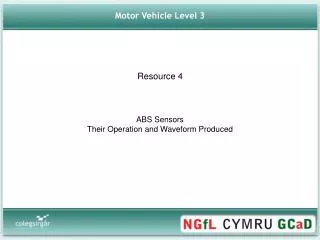
Motor Vehicle Level 3. Resource 4. ABS Sensors Their Operation and Waveform Produced. Motor Vehicle Level 3 Resource 4. ABS Sensors Their Operation and Waveform Produced. Aims. To recognize various sensors used within ABS systems and their role within the system.

E N D
Motor Vehicle Level 3 Resource 4 ABS Sensors Their Operation and Waveform Produced
Motor Vehicle Level 3Resource 4 ABS Sensors Their Operation and Waveform Produced Aims To recognize various sensors used within ABS systems and their role within the system
Motor Vehicle Level 3Resource 4 ABS Sensors Their Operation and Waveform Produced Objectives By the end of this session you will be able to: • Identify various sensors including hall, and be able to describe passive and inductive sensors and their operation • Recognize the role of the speed sensor and it's location • Recognize and comment on the waveforms produced. • Comment briefly on how to maintain the sensor, and identify possible faults.
Motor Vehicle Level 3Resource 4 ABS Sensors Their Operation and Waveform Produced Types of sensor : Active Sensor • Example:-Magnetised pick up (crankshaft sensor, ABS sensor) • Voltage signal produced is sent to the input of the ECU for analysation. • The ECU will covert this Analogue signal to Digital signal which the ECU can read. • The ECU will now react (alter the brake pressure depending on this voltage signal.
Motor Vehicle Level 3Resource 4 ABS Sensors Their Operation and Waveform Produced Types of sensor : Passive Sensor (three wire) • Three wire device • Supply voltage for the sensor is supplied via the ECU • The internal resistance alters with a change in environment these are usually used to sense movement (i.e. throttle position) • This is measured by the ECU and the ECU will alter accordingly
Motor Vehicle Level 3Resource 4 ABS Sensors Their Operation and Waveform Produced Types of sensor : Passive Sensor (two wire device) • Similar to a three wire device, the sensors internal resistance will alter with a change in environment rather than change in movement (i.e. engine coolant) • ECU Supplies voltage to the sensor, • The ECU will measure the change in internal resistance and react accordingly.
Motor Vehicle Level 3Resource 4 ABS Sensors Their Operation and Waveform Produced ABS Sensors • Of course, ABS will use an active sensor • Why do you think that is? • Could it use a passive sensor?
Motor Vehicle Level 3Resource 4 ABS Sensors Their Operation and Waveform Produced ABS Wheel Speed Sensor • Wheel Speed Sensors are mounted at each wheel and sends a rotation signal to the ECU • Wheel speed sensors can be mounted to the steering knuckle or to the axle carrier
Motor Vehicle Level 3Resource 4 ABS Sensors Their Operation and Waveform Produced ABS Wheel Speed Sensor
Motor Vehicle Level 3Resource 4 ABS Sensors Their Operation and Waveform Produced ABS Wheel Speed Sensor • As the teeth of the sensor rotor pass the iron core, magnetism will cut through the coil windings Inducing a voltage • When the tooth is centered to the iron core 0v is produced • As the tooth moves away from the iron core, the magnetic field expands producing a negative voltage • As the wheel rotates faster the voltage and frequency increase (indicating to the ECU that the vehicle is travelling faster)
Motor Vehicle Level 3Resource 4 ABS Sensors Their Operation and Waveform Produced Waveform produced • In order to diagnose a fault within an ABS system waveforms are useful in order to determine system performance, and will also give hints as to the problem.
Motor Vehicle Level 3Resource 4 ABS Sensors Their Operation and Waveform Produced Waveform produced • The following images where taking using a diagnostic tool called a Picoscope • These show two wheel speed sensors being monitored, one has a fault...is it the red trace or the blue trace?
Motor Vehicle Level 3Resource 4 ABS Sensors Their Operation and Waveform Produced Waveform produced
Motor Vehicle Level 3Resource 4 ABS Sensors Their Operation and Waveform Produced Waveform produced • this small capture taken from the waveform produced indicates a fault compared with the blue trace • The fact the we have a waveform at all indicates that the sensor is producing a signal. • Therefore, we can diagnose that the rotor wheel has failed.
Motor Vehicle Level 3Resource 4 ABS Sensors Their Operation and Waveform Produced Waveform produced • This vehicle measures rear wheel speed via a driveshaft, upon inspection, we can see that the teeth have been damaged, furthermore, we can see this corresponds to our waveform produced. • Another factor that could have produced a similar waveform could have been distance from the sensor to the rotor or contamination of the sensor.
Motor Vehicle Level 3Resource 4 ABS Sensors Their Operation and Waveform Produced Waveform produced • In order to check the voltage is correct to the sensor • Ensure that your multimeter is correct and on the correct function (direct v) • Measure between the terminals as shown (always refer to manufactures guidelines) • The voltage should be between 10v-14v
Motor Vehicle Level 3Resource 4 ABS Sensors Their Operation and Waveform Produced Probing a Sensor • Continuity check • Is done to check that there is no faults in the wiring harness between the ECU, the Actuator and the ABS relays and possibly to the sensors. • Refer to manufactures guidelines • From the signal contact in the terminal blocks check the resistance between each components. • The resistance should be around 4-6Ώ
Motor Vehicle Level 3Resource 4 ABS Sensors Their Operation and Waveform Produced Summary Have We:- • Identified various sensors including hall, and be able to describe passive and inductive sensors and their operation • Recognized the role of the speed sensor and it's location • Recognized and commented on the waveforms produced. • Commented briefly on how to maintain the sensor, and identify possible faults.