SECTIONS OF SOLIDS Part II
110 likes | 361 Vues
SECTIONS OF SOLIDS Part II. Prof.T.JEYAPOOVAN Department of Mechanical Engineering Hindustan Institute of Technology and Science Chennai-603103, India. REFERENCE BOOKS. Jeyapoovan T, “Lesson Plans for Engineering Graphics”, 2010, Vikas Publishing House Pvt Ltd, New Delhi.

SECTIONS OF SOLIDS Part II
E N D
Presentation Transcript
SECTIONS OF SOLIDSPart II Prof.T.JEYAPOOVAN Department of Mechanical Engineering Hindustan Institute of Technology and Science Chennai-603103, India www.engineeringgraphics.in
REFERENCE BOOKS Jeyapoovan T, “Lesson Plans for Engineering Graphics”, 2010, Vikas Publishing House Pvt Ltd, New Delhi. Jeyapoovan T, “Engineering Drawing and Graphics”, 2011, Vikas Publishing House Pvt Ltd, New Delhi. www.engineeringgraphics.in
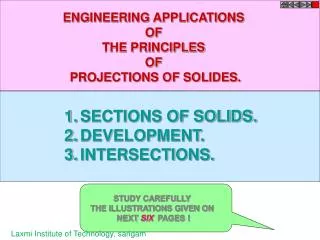
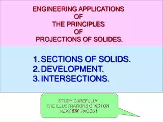
SECTION OF CONE • When a cone is cut by a section plane, the true shape of section will be a circle/ellipse/parabola/ hyperbola/triangle. • Considering equal number of generators (say 8), the true shape of section is obtained as discussed earlier. www.engineeringgraphics.in
Example 1: A cone of base diameter 50 mm and axis length 75 mm, resting on HP on its base is cut by a plane inclined at 45° to HP and perpendicular to VP and is bisecting the axis. Draw the front view and sectional top view and true shape of this section.. Draw its front view, sectional top view and true shape of section. • Draw TV, project FV of cone and assume 8 generators. Draw the trace of cutting plane at 45º to XY. • Mark the new corners in front view and project them to top view to get apparent section. • Draw new reference line X1Y1 and use the distance of new corners in TV from XY and mark from X1Y1 and join them to get the true shape of section as an ellipse. www.engineeringgraphics.in
Example 2: A cone of base diameter 60 mm and axis length 80 mm is resting on HP on its base. It is cut by a plane perpendicular to VP and parallel to a contour generator and is bisecting the axis. Draw the front view, sectional top view and the true shape section. • Draw TV and project FV, assume 8 generators. Draw trace of the cutting plane parallel the extreme generator and passing through the midpoint of the axis. • Mark new corners in FV and project them to TV. • Draw new reference line X1Y1 and use the distance of new corners in TV from XY and mark from X1Y1 and join them to get the true shape of section as a parabola. www.engineeringgraphics.in
Example 3: A cone of base diameter 60 mm and axis length 70 mm is resting on HP on its base. It is cut by a plane inclined at 45° to VP and perpendicular to HP that cuts the cone at a distance 10 mm from the axis and in front of it. Draw its top view, sectional front view and true shape of section. • Draw TV, project FV and assume 8 generators. Draw trace of the cutting plane at 45º to XY and 10mm away from axis (i.e. centre of circle in TV). • Mark new corners in TV and project them to FV. • Draw new reference line X1Y1 and use distance of new corners in FV from XY and mark from X1Y1 and join them to get the true shape of section as a hyperbola. www.engineeringgraphics.in
Example 4: A pentagonal pyramid of base side 30 mm and axis length 60 mm is resting on HP on its base with a side of base parallel to VP. It is cut by a plane inclined at 45° to VP and perpendicular to HP and is 12 mm away from the axis. Draw its top view, sectional front view and true shape of section. • Draw TV and project FV. Draw trace of the cutting plane which touching a circle of radius 12mm with the centre of the pentagon. • Mark new corners in TV and project them to FV. • Draw new reference line X1Y1 and use the distance of new corners in FV from XY and mark from X1Y1 , then join them to get the true shape of section. www.engineeringgraphics.in
Example 5: A cube of 60 mm side has its base edges equally inclined to VP. It is cut by a sectional plane perpendicular to VP, so that the true shape of cut section is a regular hexagon. Locate the plane and determine the angle of inclination of the VT with the reference line xy. Draw the sectional top view. • Draw TV and project FV of cube. Note that in TV, two sides are taken equally inclined to XY. Draw trace of cutting plane passing through the midpoint of six edges as shown. • Mark the new corners in front view and project them to top view. • Draw new reference line X1Y1 and use the distance of new corners in TV from XY and mark from X1Y1,, then join them to get the true shape of section as a hexagon. www.engineeringgraphics.in
Tips to draw Section of a Cone • Draw the projections of the cone, then draw the trace of the cutting plane. Carefully mark the new corners on the generators cut by the cutting plane, then project them to the other view. • When a cone is resting on HP on its base and the cutting plane is inclined to HP and perpendicular to VP, cuts all generators, the true shape obtained will be an ellipse. • When the cutting plane is inclined to HP and perpendicular to VP cuts a few generators and also cuts the base of cone, the true shape obtained will be a parabola. • When the cutting plane parallel to the axis of the cone, true shape obtained will be a hyperbola. www.engineeringgraphics.in
End of Lesson 8 Thank You www.engineeringgraphics.in