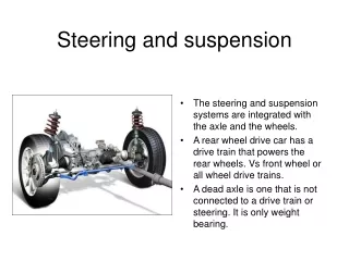
Dune Buggy Suspension and Steering Design
380 likes | 949 Vues
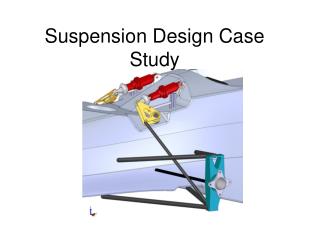
Dune Buggy Suspension and Steering Design. Nate Dobbs Steve Myers Faculty Mentor: Dr. Richard Hathaway Industrial Mentor: David Myers. Overview. Problem Goals of Project Terminology Analysis Optimization Final Design. Current Design Instability. Current Suspension Shortfalls.

Dune Buggy Suspension and Steering Design
E N D
Presentation Transcript
Dune Buggy Suspension and Steering Design Nate Dobbs Steve Myers Faculty Mentor: Dr. Richard Hathaway Industrial Mentor: David Myers
Overview • Problem • Goals of Project • Terminology • Analysis • Optimization • Final Design
Goals of Project • Re-design current front suspension and steering. • Maximize performance in a sand environment by optimizing: • Camber Gain • Bump Steer • Roll Center Height • Ackermann Steering • Toe-In
Existing Suspensions • Volkswagen Trailing arm - most common Swing-Arm – Original Design
Camber Gain • Tilt of wheels towards vehicle. • Ideal setup keeps wheels perpendicular to ground.
Bump Steer • The tie rod path follows a fixed radius. • Wheel travels on a separate path • The difference in these two causes the wheel to turn. Steering Tie Rod Path Wheel Travel Rack and Pinion
Roll Center Suspension Geometry • Point at which Lateral Loads act upon the vehicle • Angle dictates force distribution • Location change is critical Roll Center and Center of Gravity Locations Front Wheels Center of Gravity Roll Center
Effects of Roll Center Height on Suspension • Roll Center to C.G. distance is related to force seen by springs/dampers • The distance from the ground to the roll center is force seen by the geometry. 40% 60%
Ackermann Steering • Steering angles to travel perfect concentric circles • Shown in the form of a percentage. • Ackermann angle is between the two wheels • 0% is with parallel front wheels
Rack & Pinion Selection • The rack and pinion changes rotational motion of the steering wheel into linear motion. • Ford Escort Rack and Pinion was 2.45:1 ratio. • 1 revolution of the wheel resulted in 2.45 inches of linear travel.
Rack & Pinion Selection • A smaller ratio means more movement to make a tight turn. • A 5:1 ratio rack and pinion was incorporated into the design • Full Range of Wheel motion in less than one full turn of the wheel.
Benchmark (Trailing Arm) • Excellent for minimal camber gain. • Inexpensive and widely available. • Poor Bump Steer characteristics. • Poor Adjustability.
Original Design • Swing Arm configuration. • Custom – more expensive, not adjustable • Unacceptable Bump-Steer
SuspensionGen Analysis • Trailing Arm configuration from benchmark data. • Could not analyze 12 inches of travel. • Poor results in all areas.
SuspensionGen Analysis • Original Swing-Arm Model • Poor results at extremes of suspension travel • Large Camber Gain, bump-steer
Final Design Optimization • 17 configurations were evaluated • Varied A-arm location points within geometry. • Selection 3D gave the best results. • Optimized Camber Gain • Good Roll Center Height • Poor Toe-in and Bump Steer
Steering Arms • Steering arm length graphed with turning radius. • Based on 20% Ackermann configuration. • 12 foot turning radius was desired. • This resulted in a 5 inch steering arm.
Bump steer and toe-in vary with rack positioning. Angle between tie rod and wheel axis gives Ackermann Steering The steering arm and suspension move about similar radius, minimizing bump steer. Bump Steer/Toe-in Analysis
SuspensionGen Analysis • Final Design • Analysis performed with 12 inches of travel. • Good results in roll and vertical displacement.
Finite Element Analysis • AISI 1020 Steel was used due to availability and cost. • FEA analysis was used to determine material size • Shows results of these forces in displacements and stresses. • A 0.189 inch wall thickness tubing was used and allowed for a significant factor of safety.
Review • Sand Dune Buggy Stability • Evaluated 3 designs • Developed Short-Long Arm Solution • Optimized Geometry, Steering, and handling characteristics • All original goals were met.