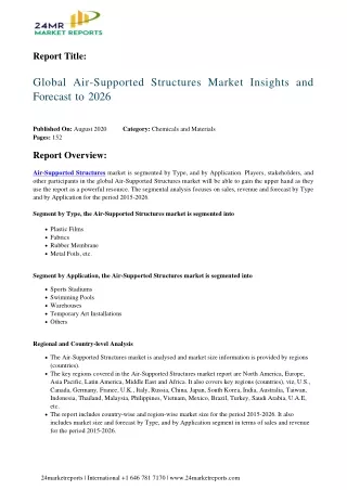
Adapting Air-Supported Structures for Ground-Based EM Applications
450 likes | 478 Vues
Explore various options for utilizing air-supported structures in electromagnetic field survey systems, analyzing feasibility and engineering constraints. Concepts include inflatable structures with coils, fabrications using inflatable boat techniques, and stability enhancements using tubes and additional features.

Adapting Air-Supported Structures for Ground-Based EM Applications
E N D
Presentation Transcript
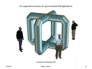
Air supported structures for ground-based EM applications A study for Berkeley EM Robin Lafever
The following is a quick study of some of the options for adapting air-supported structures to E. M. field survey systems. The concepts presented all have feasibility, at first glance, and most of these structures have been built and used for other purposes. Each concept assumes a specific manufacturing technique, which in turn, defines the engineering constraints and limits to size, mass, and materials. In all cases, I assumed a typical Transmitter coil cross-section to be 6 turns of 10 mm dia. Copper. Thermal issues were ignored. A goal was to get maximum transmitter planar cross-section. Another goal was to consider only systems that could be handled by a 2-man crew; could be set up, operated, and taken down in one day; and would fit into a pickup truck or van. Robin Lafever
8 X 10 Coil set 10’ Starting with a typical Coil, ~80 SF included Area, 6 Turns, 10mm Litz wire, For example…. X 2.. Perpendicular to each other. 8’ Robin Lafever
8 X 10 Coil set Coil elements are fabricated onto a substrate so that they can be installed onto an inflated structure. ( Zipper pocket ) Robin Lafever
8 X 10 Coil set Inflated structure with coils. Fabricated using inflatable boat manufacturing techniques. Robin Lafever
8 X 10 Coil set This model is 8’ high X 10’ long in each axis. Shown here, it has an 18” diameter Cross-section and will require a 5-10 psi Internal pressure to remain stable. It can be inflated with compressed air or a hand-pump. It will weigh < 100 lbs. Inflatable boat fabrication technology will result in a robust structure well suited To fieldwork. Robin Lafever
8 X 10 Coil set Stability can be enhanced by adding features and geometry Robin Lafever
8 X 10 Coil set This version uses 12” dia. Tubes. It will need 5-10 psi, and will still be floppy at the corners Robin Lafever
8 X 10 Coil set Additional features will help. The web could be realized as struts, or cables as well. Robin Lafever
8 X 10 Coil set …and, you get ~75 sq. ft. per transmitter plane. 75 sq. ft. Robin Lafever
Scaling Up…….. Robin Lafever
Scaling Up…….. Same fabrication technique, twice as big. This 16’ X 20’ model may be near a practical limit for the ‘Inflatable boat’ technique Robin Lafever
16’ X 20’ cross form This is getting to be >200 lbs, but might still be within the practical envelope of the inflatable-boat technique. At this scale, however, WIND is a consideration. This will certainly have to be tethered to the ground. Robin Lafever
16’ X 20’ cross form Robin Lafever
16’ X 20’ cross form Robin Lafever
16’ X 20’ cross form ..And you get 310 sq. ft. Robin Lafever
16’ X 20’ cross form.. Another take. This model is built like an Inflatable Boat; Heavy, durable fabrics, and requires 5-10 psi to remain stable This model is fabricated like a ‘Bounce House’ Light flexible fabrics, requires <1 psi to remain stable Inflated with a hand pump or compressed air Inflated with a fan Robin Lafever
16’ X 20’ cross form.. Another take. This is still pretty light. ~100 lbs And it will roll up and fit into a pickup truck Robin Lafever
16’ X 20’ cross form.. Another take. Coils are shown way oversized. In real life, they cannot get too heavy Robin Lafever
16’ X 20’ cross form.. Another take. 311 sq. ft. Robin Lafever
Scaling Up another notch….. Robin Lafever
25’ X 30’ X 70’ multi coil These both may be made using the same techniques and materials, but there are other options at this scale. Robin Lafever
25’ X 30’ X 70’ multi coil I have built several of these, at this scale, over the years. They work. A range of materials are appropriate here, from High-strength air-tight fabrics to low-cost industrial films. It is even feasible to consider designing the inflation envelope as a short-life, disposable unit. Inflation pressure is very low, < 1 psi The fan shown is actually too much. Robin Lafever
1195 sq. ft. Robin Lafever
490 sq. ft. Robin Lafever
Scaling up some more… These are all thin-membrane, low-pressure structures. Again, at this scale, wind is a consideration. These must all be tethered to the ground. I think this is way too big to handle in this shape. I have built some at this scale, but not this shape. I have built these, at this scale. Robin Lafever
20’ X 20” Cube , and 30’ X 30’ Cube The cubes are not very stable. They get mushy at the corners And try to become spheres. Internal webs will help, as will higher pressures, and light Tx cables Robin Lafever
20’ X 20” Cube , and 30’ X 30’ Cube In any event, you get: 1244 sq. ft. 537 sq. ft. Robin Lafever
Even further….. Special note: At this scale, the internal air temperature begins to make a difference. If it gets high enough relative to the outside air, the bodies will begin to unload, or even take off. Robin Lafever
Even further…. I’m sure you saw this coming ..a hot-air lifting body. This is about the smallest scale that this might be practical. I have built some of these at smaller scale, with thin film membranes. The volume has to be large enough to overcome the weight of the fabric its made of, plus payload. Fabric strength drives you to larger volumes Robin Lafever
Hot-air Lifting body Robin Lafever
Hot-air Lifting body 30’ wide X 130’ long Conceived as a modified Hot-air balloon envelope, This can also be rendered as a thin-membrane structure. Tethered to the ground, of course, and inflated with heated air. Robin Lafever
Hot-air Lifting body 30’ wide X 130’ long 1104 sq. ft. Robin Lafever
And finally…. Yer basic Hot-air balloon. Robin Lafever
Tethered Hot-air Balloon Yer basic Hot-air balloon. Pretty much right out of the factory with a few modifications. This one is 50’ dia. and could be made bigger and in more defined shapes. Robin Lafever
Tethered Hot-air Balloon Yer basic Hot-air balloon. Pretty much right out of the factory with a few modifications. This one is 50’ dia. and could be made bigger and in more defined shapes. It is tethered to the ground, inflated by heated air from a fan, and will still stuff into a medium sized van. Since there is no airworthyness requirement, you can get used ones cheap. Robin Lafever
Tethered Hot-air Balloon ~1800 sq. ft. / plane Yer basic Hot-air balloon. Pretty much right out of the factory with a few modifications. This one is 50’ dia. and could be made bigger and in more defined shapes. It is tethered to the ground, inflated by heated air from a fan, and will still stuff into a medium sized van. Since there is no airworthyness requirement, you can get used ones cheap. Robin Lafever
~1800 sq. ft. 1104 sq. ft 1244 sq. ft. 1195 sq. ft. ( LONG AXIS ) 311 sq. ft. 537 sq. ft. 310 sq. ft. 490 sq. ft. ( SHORT AXIS ) 75 sq. ft. Summary All of these, in final form, could be handled by a 2-man crew, or less. They will fit into a truck. The envelopes could easily be in the 75 lb. to 200 lb. range..for all of them! Materials and manufacturing techniques fall into three groups defined, approximately, by scale: Inflatable Boat technology ‘Jump House’ technology Hot-air Balloon technology Robin Lafever
Processes / fabrication technique / material / scale The notions explored here fall into three neat categories, with overlap. 1. High pressure, heavy tough materials, inflated by compressed air. Made using Inflatable Boat technology 2. Low-pressure, light fabrics or films, inflated by fan. Made using ‘Jump House technology’ **Can also me made using thin-film technologies, . 3. Very low pressure, specialized fabrics, inflated by fan with hot air assist Made using Hot-air Balloon technology Robin Lafever
Next steps A simple next step is to match the capabilities implied by these concepts to an application that needs that capability. We already have several, lets test them against these ideas. A more specific, application driven conceptual design is an easy next step. It will provide detailed raw info to the Vendors and Clients for reality checks, quotes, and schedules. A Proof-of-concept demonstration is an obvious first tangible article for further development of any field device. We have already done some of the homework in this direction. Focusing on an application will allow us to capitalize on that and proceed to real hardware. It may be possible, in some cases, to do effective POC demos before we commission a field prototype. I’ll explain on the next page. Robin Lafever
Next steps with detail We have already explored the feasibility of Boat-tech structures at similar scales for our Airborne EM study, gotten reality checks from prototype fabricators and pronounced the feasibility good. A next step would be to show the Vendor a concept design. Jump-house vendors seem to be in abundance, and I am familiar with the basic geometry and fabrication constraints. Specific reality checks could be straightforward. **Jump-Houses are available for rent, in approximately the scale and shape we want. A next step could be to rig a temporary POC demo by draping coils onto an existing Jump-House. Hot-air Balloon vendors are also in abundance, including homebuilders. Custom designs are common. Again, reality checks could be straightforward. **Used Balloon envelopes, and whole systems, are available at low-cost, especially since we have no airworthiness requirement. A next step would be to attach coils to an envelope, rig a temporary POC demo. Homebuilt prototypes are within our scope. Robin Lafever
Another Option Availability of industrial films and tapes make it feasible to hand fabricate structures like these, as long as the shapes remain simple. As mentioned earlier, I have made and used many of these. At this scale. Two people can fabricate this envelope in one day for < $1000 in materials. Upgrades in materials and craftsmanship will extend the useful life. Robin Lafever
Conclusions All these concepts, in some form, could be feasible as ground-based E. M. platforms. All of these concepts already exist in similar forms for other uses. All of these forms have a clear path to design, fabricate, and test field models. Some of these could be taken to the Proof-of-concept stage for surprisingly modest effort and cost. A few we should keep for ourselves. Robin Lafever March 2010 Robin Lafever
Jump-House These are 13’ X 13’, rent for < $100/ day. Design and fab your own < $10 K ? http://www.myjump4joy.com/jumpers.html Robin Lafever
Other stuff I didn’t look into domes, tents, and display structures at all, but they are out there…. Robin Lafever