Chapter 2A: Hardware systems and LPARs
Chapter 2A: Hardware systems and LPARs. Objectives. In this chapter you will learn: About S/360 and zSeries hardware design Mainframe terminology Hardware componentry About processing units and disk hardware How mainframes differ from PC systems in data encoding

Chapter 2A: Hardware systems and LPARs
E N D
Presentation Transcript
Objectives • In this chapter you will learn: • About S/360 and zSeries hardware design • Mainframe terminology • Hardware componentry • About processing units and disk hardware • How mainframes differ from PC systems in data encoding • About some typical hardware configurations
Introduction • Here we look at the hardware in a complete system although the emphasis is on the processor “box” • Terminology is not straightforward • Ever since “boxes” became multi-engined, the terms system, processor, and CPU have become muddled
Early system design • System/360 was designed in the early 1960s • The central processor box contains the processors, memory, control circuits and channel interfaces • Early systems had up to 16 channels whereas modern systems have 1024 (256 * 4 Logical Channel Subsystems) • Channels connect to control units • Control units connect to devices such as disk drives, tape drives and communication interfaces
Device address • In the early design the device address was physically related to the hardware architecture • Parallel channels had large diameter heavy copper “bus and tag” cables • This addressing scheme is still in use today only vituralized
Parallel Channel “Connectivity” • The maximum data rate of the parallel channel is up to 4.5 MB, and the maximum distance that can be achieved with a parallel channel interface is up to 122 meters (400 ft). • These specifications can be limited by the connected control units and devices.
Current design • Current CEC designs are considerably more complex although modular in their architecture to allow for easy maintenance and upgrades then the early S/360 design • This new design includes: - CEC modular componentry - I/O housing - I/O connectivity - I/O operation - Partitioning of the system
Air flow front to rear Two Models for System z10 – Physical Dimensions Business Class (BC) Enterprise Class (EC) 79.3 Air flow front to rear 71.1 61.7 30.9 (inches) (inches) Model 2098 Model 2097
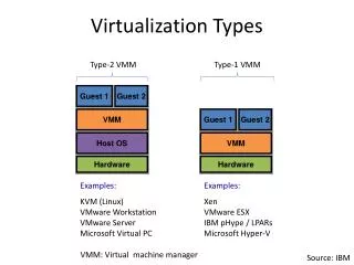
Innovative designs Business Class design is based on Drawers Enterprise Class design is based on Books • One drawer houses the Central Processing Complex (CPC) • One to four drawers house the I/O features. • Up to four Books house the Central Processing Complex • One to three cages house the I/O features
Recent Configurations • Most modern mainframes use switches between the channels and the control units. • The switches are dynamically connected to several systems, sharing the control units • and some or all of its I/O devices across all the systems. • Multiple partitions can sometimes share channel addesses known as spanning.
ESCON Connectivity • ESCON (Enterprise Systems Connection) is a data connection created by IBM commonly • used to connect their mainframe computers to peripheral devices. • ESCON replaced the older, slower parallel Bus&Tag channel technology • The ESCON channels use a director to support dynamic switching.
ESCON Director ESCD ESCD I/O switch capable of providing dynamic, nonblocking, any-to-any connectivity for up to 60 fiber optic links operating at 200 Mb/s
Fiber Connectivity (FICON) • FICON (for Fiber Connectivity) was the next generation high-speed input/output (I/O) interface • used to connect mainframe computer to storage devices. • FICON channels increase I/O capacity through the combination of a new architecture and • faster physical link rates to make them up to eight times as efficient as ESCON • (Enterprise System Connection),
ESCON vs FICON • ESCON - 20 Mbytes / Second - Lots of “dead time”. One active request at a time. - One target control unit • FICON - 400 Mbytes / Second, moving to 800 - Uses FCP standard - Fiber Optic cable (less space under floor) - Currently, up to 64 simultaneous “I/O packets” at a time with up to 64 different control units - Supports Cascading switches
System z I/O Connectivity • ESCON and FICON channels • Switches to connect peripheral devices to more than one CEC • CHPID addresses are two hex digits (FF / 256) • Multiple partitions can share CHPIDs (MIF) • I/O subsystem layer exists between the operating system and the CHPIDs
MIF Channel Consolidation - example statically dynamically assigned assigned
I/O Connectivity Addressing and Definitions • I/O control layer uses a control file IOCDS that translates physical I/O addresses into devices numbers that are used by z/OS • Device numbers are assigned by the system programmer when creating the IODF and IOCDS and are arbitrary (but not random!) • On modern machines they are three or four hex digits example - FFFF = 64K devices can be defined • The ability to have dynamic addressing theoretically 7,848,900 maximum number of devices can be attached.
= = = = @ @ @ @ Channel Subsystem Relationship to Channels, Control Units and I/O Devices Z10 Controls queuing, de-queuing, priority management and I/O identification of all I/O operations performed by LPARs Supports the running of an OS and allows CPs, memory and Subchannels access to channels This represents an I/O device to the hardware and is used by the OS to pass an I/O request to the channel subsystem The communication path from the channel subsystem to the I/O network and connected Control Units/devices Channel Subsystem Partitions Subchannels Channels Control Units Devices (disk, tape, printers) CU CU CU
MBA MBA MBA SAP SAP SAP H I P E R V I S O R H S A Cache Cache Cache Cache MBA SAP Logical-channel Subsystem 1 Logical-channel Subsystem 2 Logical-channel Subsystem 3 Physical-Channel Subsystem - One ESCON channel shared by all partitions configured to LCS15 - A MIF-shared channel path -One FICON channel shared by all LCSs and all partitions • -A MCSS-Spanned Channel Path Logical-channel Subsystem 0 FICON Switch, Control Unit, Devices, etc. ESCON Switch, Control Unit, Devices, etc. The Mainframe I/O Logical Channel Subsystem Schematic
System z – I/O Configuration Support Each Logical Channel Subsystem has a set of Subchannels System z Processor LogicalChannel Subsystem LogicalChannel Subsystem Partitions Partitions Subchannels Subchannels 63K 63K Channels Channels
System Control and Partitioning Support Elements (SEs) Either can be use to configure the IOCDS The IBM mainframe can be partitioned into separate logical computing systems
LPAR – Logical Partition • System resources can be divided or shared among many independent logical partitions (LPARs) • Controlled by the LPAR hypervisor • Comes with the standard Processor Resource/Systems Manager (PR/SM) • Software layer to manage multiple operating sysems running in a single central processing complex. • Can have up to 60 LPARs in a mainframe • Limited by memory size, I/O availability, and available processing power • Each LPAR is considered an isolated and distinct server that supports an instance of an OS
A system programmer can assign different operating environments to each partition with isolation • An LPAR can be assigned a number of dedicated or shared processors. • Each LPAR can have different central storage (CSTOR) assigned depending on workload requirements. • CSTORs cannot be shared among LPARs. • The I/O channels (CHPIDs) are assigned either statically or dynamically as needed by server workload. • Provides an opportunity to consolidate distributed environments to a centralized location Logical Partitions (LPARs) or Servers • CSTOR can also be referred to as main storage • Directly addressable • Both data and programs must be loaded in CSTOR
Characteristics of LPARs • LPARs are the equivalent of a separate mainframe for most practical purposes • Each LPAR runs its own operating system • Devices can be shared across several LPARs • Processors can be dedicated or shared • When shared each LPAR is assigned a number of logical processors (up to the maximum number of physical processors) • Each LPAR is independent
LPAR Logical Dispatching (Hypervisor) 1 - The next logical CP to be dispatched is chosen from the logical CP ready queue based on the logical CP weight. 2 - LPAR LIC dispatches the selected logical CP (LCP5 of MVS LP) on a physical CP in the CPC (CP0, in the visual). 3 - The z/OS dispatchable unit running on that logical processor (MVS2 logical CP5) begins to execute on physical CP0. It executes until its time slice (generally between 12.5 and 25 milliseconds) expires, or it enters a wait, or it is intercepted for some reason. 4 - In the visual, the logical CP keeps running until it uses all its ime slice. At this point the logical CP5 environment is saved and control is passed back to LPAR LIC, which starts executing on physical CP0 again. 5 - LPAR LIC determines why the logical CP ended execution and requeues the logical CP accordingly. If it is ready with work, t is requeued on the logical CP ready queue and step 1 begins again.
LPAR Summary • System administrators assign: • Memory • Processors • CHPIDs either dedicated or shared • This is done partly in the Input/Output Configuration Data Set (IOCDS) and partly in a system profile on the Support Element (SE) in the CEC. This is normally updated through the Hardware Management Console (HMC). • Changing the system profile and IOCDS will usually require a power-on reset (POR) but some changes are dynamic
Processor units or engines Today’s mainframe can characterize workloads using different license engine types • General Central Processor (CP) • - Used to run standard application and system workloads • System Assist Processor (SAP) • - Used to schedule I/O operations • Integrated Facility for Linux (IFL) • - A processor used exclusively by a Linux LPAR under z/VM. • z/OS Application Assist Processor (zAAP) • - Provides for Java and XML workload offload • z/OS Integrated Information Processor (zIIP) • - Used to optimize certain database workload functions and • XML processing • Integrated Coupling Facility (ICF) • - Used exclusively by the Coupling Facility Control Code (CFCC) • providing resource and data sharing • Spares • - Used to take over processing functions in the event of an engine failure Multi Chip Module (MCM) Note: Channels are RISC micro processors and are assigned depending on I/O configuration requirements.
Capacity on Demand • Various forms of Capacity on Demand exist • Additional processing power to meet unexpected growth or sudden demand peaks • CBU – Capacity Back Up • CUoD – On/Off Capacity Upgrade on Demand • SubCapacity Licensing Charges • LPAR CPU Management (IRD)
Disk Devices • Current mainframes use 3390 disk devices • The original configuration was simple with a controller connected to the processor and strings of devices attached to the back end
RAID (1) No redundancy, increase performance • Raid levels 0 through 2 • Backup and parity drives are shaded Creates an exact copy Stripes data at bit level and uses Hamming code
RAID (2) Byte-level striping with dedicated parity disk • Raid levels 3 through 5 • Backup and parity drives are shaded Block-level striping with dedicated parity disk Block-level striping with parity distributed across disks
Modern 3390 devices • The DS8000 2105 Enterprise Storage Server just shown is very sophisticated • It emulates a large number of control units and 3390 disks. It can also be partitioned and connect to UNIX and other systems as SCSI devices. • There are 11 196 TB of disk space up to 32 channel interfaces, 16 256 GB cache and 284 MB of non-volatile memory
Modern 3390 Devices • The physical disks are commodity SCSI- type units • Many configurations are possible but usually it is RAID-5 arrays with hot spares • Almost every part has a fallback or spare and the control units are emulated by 4 RISC processors in two complexes.
Modern 3390 Devices • The 2105 offers FlashCopy, Extended Remote Copy, Concurrent Copy, Parallel Access Volumes, Multiple Allegiance • This is a huge extension of the original 3390 architecture and offers a massive performance boost. • To the z/OS operating system these disks just appear as traditional 3390 devices so maintaining backward compatibility
EBCDIC • The IBM S/360 through to the latest zSeries machines use the Extended Binary Coded Decimal Interchange character set for most purposes • This was developed before ASCII and is also an 8 bit character set • z/OS Web Server stores ASCII data as most browsers run on PCs which expect ASCII data • UNICODE is used for JAVA on the latest machines
Clustering • Clustering has been done for many years in several forms • Basic shared DASD • Channel-toChannel/Global Resource Sharing (CTC/GRS( rings • Basic and Parallel sysplex • Image is used to describe a single z/OS system, which might be standalone or an LPAR on a large box
Basic shared DASD • Limited capability • O/S issues reserve and release against a whole disk • Limits access to that disk for the duration of the update
Next few slides introduce Sysplex and Parallel Sysplex or Instructor can use Slides in Chapter02B for more details
Basic System Complex (Sysplex) Can have up to 32 systems joined into a cooperative single unit • Global Resource Sharing (GRS) used to pass information between systems via the Channel-To-Channel ring • Request ENQueue on a dataset, update, then DEQueue • Loosely coupled system
Parallel Sysplex A parallel sysplex can provide near continuous availability • This extension of the CTC ring uses a dedicated Coupling Facility to store ENQ data for GRS • This is much faster • The CF can also be used to share application data such as DB2 tables • Can appear as a single system
Parallel Sysplex Attributes • Dynamically balances workload across systems with high performance • Improve availability for both planned and unplanned outages • Provide for system or application rolling-maintenance • Offer scalable workload growth both vertically and horizontally • View multiple-system environments as a single logical resource • Use special server time protocol (STP) to sequence events between servers
Typical Systems • This shows two very small systems • On the left is a Multiprise 3000, which was designed for small installations with internal disk drives • On the right is a FLEX-ES emulation system, which runs on a PC running Linux or UNIX
Summary • Terminology is important • The classic S/360 design is important as all later designs have enhanced it. The concepts are still relevant • New processor types are now available to reduce software costs • EBCDIC character set • Clustering techniques and parallel sysplex